Climate controlled seat

a seat and climate control technology, applied in the direction of chairs, pedestrian/occupant safety arrangements, vehicular safety arrangements, etc., can solve the problems of existing climate control systems, seat occupants' back and other pressure points may remain sweaty, and the seat is very hot and uncomfortable for a long tim

Inactive Publication Date: 2006-09-07
LOFY JOHN +2
View PDF40 Cites 68 Cited by
  • Summary
  • Abstract
  • Description
  • Claims
  • Application Information

AI Technical Summary

Problems solved by technology

For example, an automotive vehicle exposed to the summer weather, where the vehicle has been parked in an unshaded area for a long period of time, can cause the vehicle seat to be very hot and uncomfortable for the occupant for some time after entering and using the vehicle, even with normal air conditioning.
Furthermore, even with normal air-conditioning, on a hot day, the seat occupant's back and other pressure points may remain sweaty while seated.
There are, however, other problems that have been experienced with existing climate control systems for seats.
For example, some climate control systems are not easily integratable into existing seat construction methods.
Such systems require a significantly greater number of parts as compared to existing automotive seats, and often require complex mechanical parts.
In the past, this has resulted in increased costs for individualized occupant cooling in automobiles.
Also, the mechanical comfort of the seat is appreciably affected in the systems employed, as compared to the comfort provided by standard automotive seats.
Further, the current techniques are problematic because they may limit the ability for vehicle designers to provide modern seating embodiments and stylistic designs.

Method used


Image

  • Climate controlled seat
  • Climate controlled seat
  • Climate controlled seat

Examples


Embodiment Construction

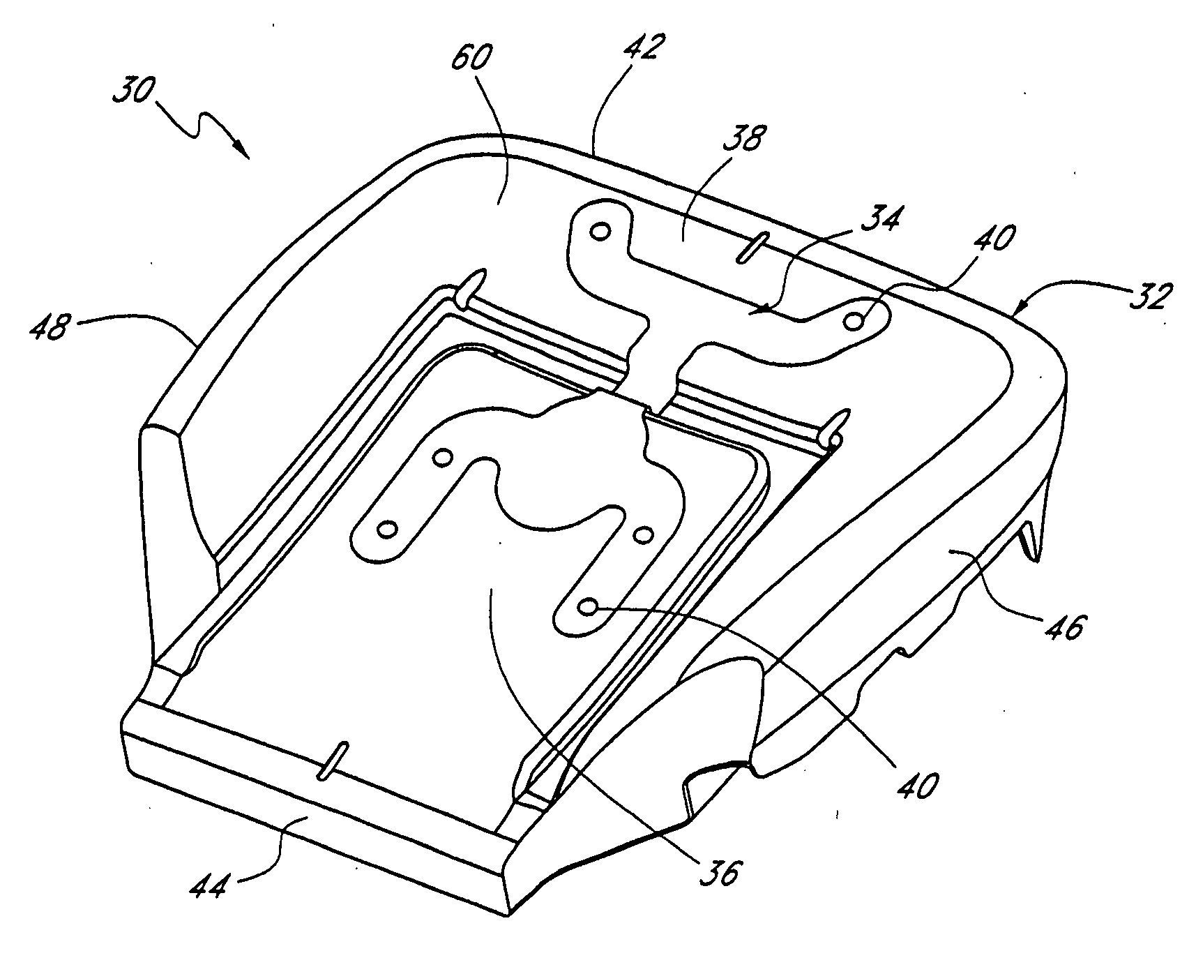
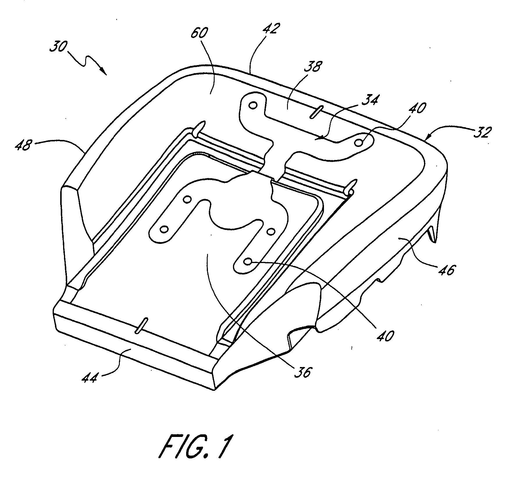
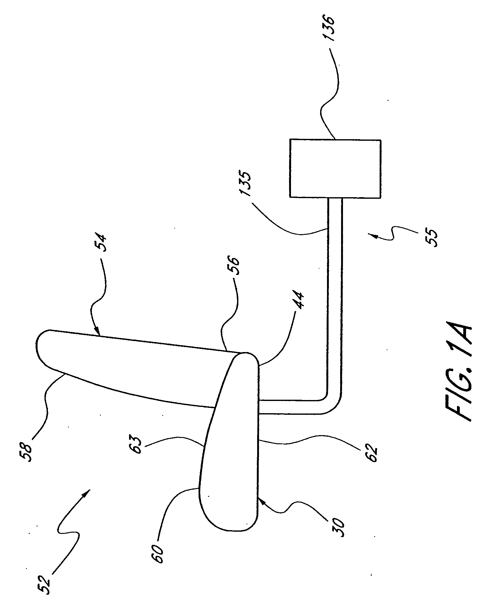
[0031] The preferred embodiments described herein generally relate to seats in the form of vehicle or automotive seats. Generally a vehicle seat can have a seat bottom and seat back. In some embodiments, the seat bottom can have an insert located between the seat upholstery and the seat cushion. The insert can be in fluid communication with the cabin space of the vehicle. Air can flow through the insert and out of the seat to control the climate around the person in the seat. The insert can also be used to remove air from the cabin of the vehicle. The air can then pass through the insert and is delivered to a fluid line.

[0032] To assist in the description of the disclosed embodiments, words such as upward, upper, downward, lower, vertical, horizontal, upstream, and downstream are used to describe the accompanying figures. It will be appreciated, however, that the illustrated embodiments can be located and oriented in a variety of desired positions.

[0033]FIG. 1 illustrates an exemp...


PUM

PropertyMeasurementUnit
hydraulic diameteraaaaaaaaaa
widthaaaaaaaaaa
distanceaaaaaaaaaa

Abstract

A vehicle seat has a seat bottom and seat back. The seat bottom can have a ventilated insert located between the seat upholstery and the seat cushion. The inset can be in fluid communication with the cabin space of the vehicle. In one arrangement, the insert has a cover with holes and a body. The cover and body cooperate to form a plurality of plenums for passing air through the insert. A fluid system can deliver air to the insert so that the air passes through the plenums and directed out of the holes in the cover. The air then flows out of the vehicle seat to control the climate around the person in the seat. The insert can also be used to remove air near the seat by drawing air proximate the seat into the insert. The air can then pass through the insert and is delivered to the fluid system.

Description

PRIORITY INFORMATION [0001] This application is a continuation of U.S. patent application Ser. No. 10 / 853,779, filed May 25, 2004, the entire contents of which is hereby incorporated by reference herein.BACKGROUND OF THE INVENTION [0002] 1. Field of the Invention [0003] This invention relates to climate control. More specifically, this invention relates to climate control of a seat. [0004] 2. DESCRIPTION OF THE RELATED ART [0005] Temperature modified air for environmental control of living or working space is typically provided to relatively extensive areas, such as entire buildings, selected offices, or suites of rooms within a building. In the case of vehicles, such as automobiles, the entire vehicle is typically cooled or heated as a unit. There are many situations, however, in which more selective or restrictive air temperature modification is desirable. For example, it is often desirable to provide an individualized climate control for an occupant seat so that substantially ins...

Claims


Application Information

Patent Timeline
Patent Type & Authority Applications(United States)
IPC IPC(8): A47C7/72A47C31/00A47C7/02B60N2/42B60N2/56B60R21/00
CPCB60N2/5628Y10T29/481B60N2/5657B60N2/565
Inventor LOFY, JOHNJACKSON, TODDTERECH, JOHN
Owner LOFY JOHN
Why Eureka
Try Eureka