Method for forming different liquid crystal twist angle

a liquid crystal display and twist angle technology, applied in non-linear optics, instruments, optics, etc., can solve the problems of increasing the power consumption of backlight and consuming a large portion of the total power consumed by the liquid crystal display device, and achieve different luminescence efficiencies and maximize the total luminance

Inactive Publication Date: 2006-09-07
TPO DISPLAY
View PDF5 Cites 0 Cited by
  • Summary
  • Abstract
  • Description
  • Claims
  • Application Information

AI Technical Summary

Benefits of technology

[0007] Because differences in liquid crystal twist angle may realize different luminescence efficiencies, the main purpose of the present invention is to provide a manufacture method of liquid crystal display to employ different liquid crystal twist angles in the reflection and transmission regions to maximize the total luminance. The liquid crystal display of the present invention may transmit a part of incident light and reflects the rest so that it can be used when the ambient light is weak while maintaining the advantages of the reflection type liquid crystal display.

Problems solved by technology

In such a transmission type liquid crystal display device, however, the backlight consumes a large portion of the total power consumed by the liquid crystal display device.
This further increases the power consumption of the backlight and thus the resultant liquid crystal display device.

Method used


Image

  • Method for forming different liquid crystal twist angle
  • Method for forming different liquid crystal twist angle
  • Method for forming different liquid crystal twist angle

Examples


first embodiment

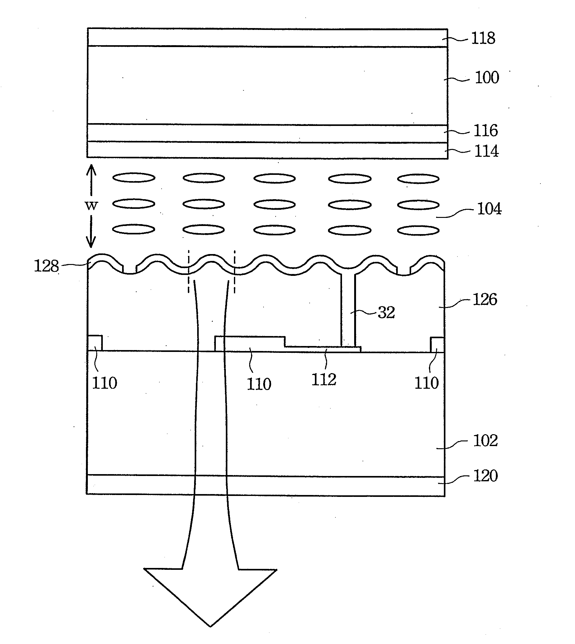
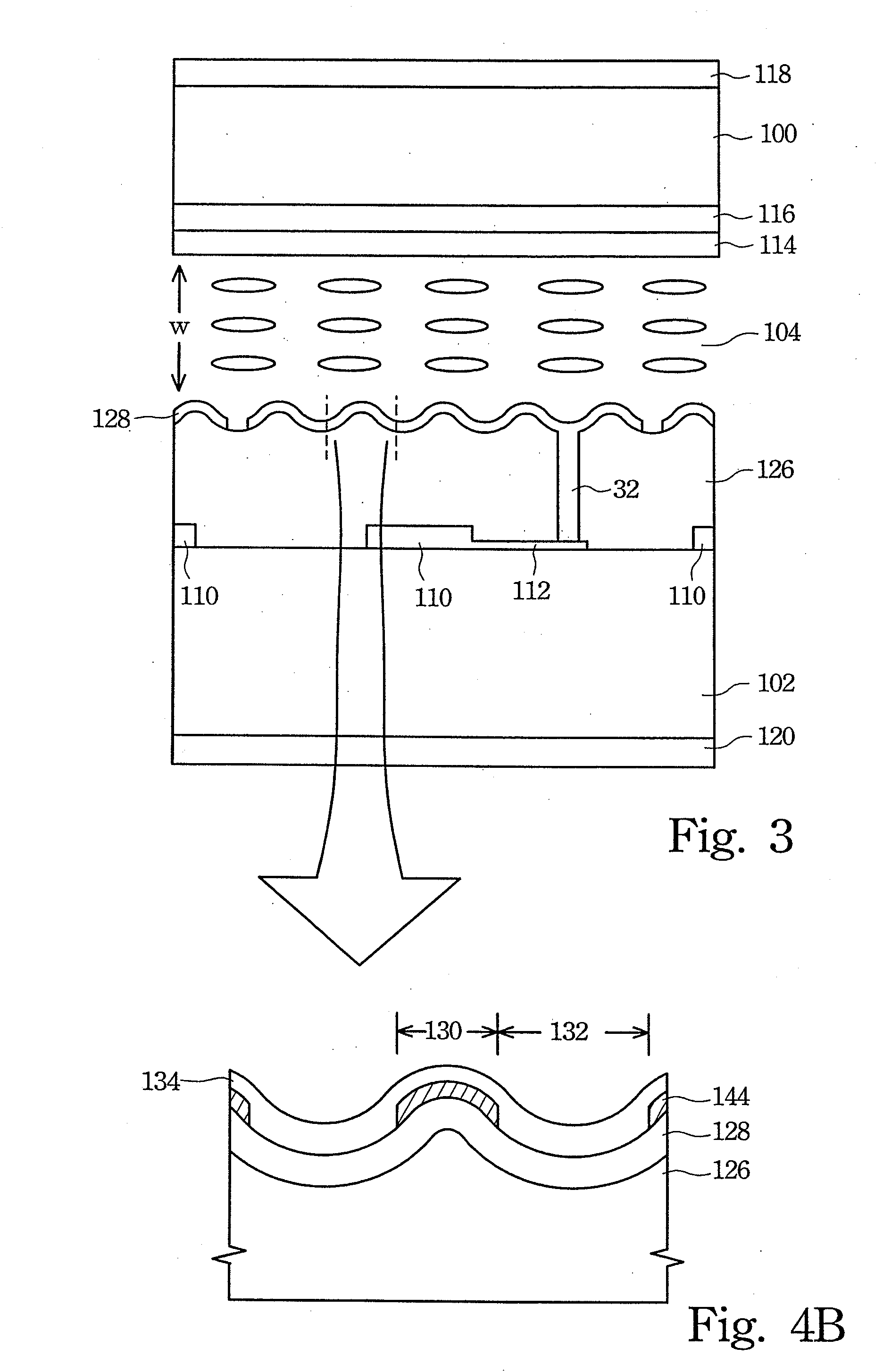
[0027] The rubbing method is used to arrange the orientation in the The rubbing process adjusts and determines the orientation of the orientation layer that may arrange the liquid crystal molecules according to the determined orientation. The present invention uses different rubbing pressures to adjust and determine the orientation of the reflection region 130 and transmission region 132, as shown in FIG. 4. For example, because the transmission region 132 is located in the recess of the concave and convex structure, the higher rubbing pressure is used to adjust and determine the orientation of this region. The orientation is adjusted and determined in the reflection region 130 and the transmission region 132 at the same time due to the higher rubbing pressure.

[0028] Conversely, because the reflection region 130 is located in the convex portion of the concave and convex structure, the lower rubbing pressure is used to adjust and determine the orientation of this region. The transmi...

second embodiment

[0032] the present invention uses the UV alignment method. The method uses UV light having an identical polarized direction to arrange the respective orientations of the orientation layers formed over the reflection region 130 and transmission region 132.

[0033] Referring to FIG. 7A, the orientation of the reflection region 130 is first arranged. The UV light 142A having an identical polarized direction as required orientation on the reflection region 130 is used to arrange the orientation of the orientation layer 134. Because the UV light illuminates the whole orientation layer 134, the transmission region 132 and the reflection region 130 have the same arranged orientation.

[0034] Referring to FIG. 7B, the orientation of the transmission region 132 is arranged next. The UV light 142B having an identical polarized direction as the required orientation on the transmission region 132 is used from the back to illuminate the orientation layer 134 to arrange the orientation. Although the...


PUM

PropertyMeasurementUnit
twist angleaaaaaaaaaa

Abstract

Different liquid crystal twist angles realize different luminescence efficiencies for reflection and transmission regions, respectively. Therefore, the difference of liquid crystal twist is used in reflection and transmission region, respectively, of a liquid crystal display to maximize their luminescence efficiency so that the total luminescence may reach the optimum state.

Description

RELATED APPLICATIONS [0001] The present application is a divisional of U.S. patent application Ser. No. 10 / 656,122, filed Sep. 8, 2003 which is based on, and claims priority from, Taiwanese Application Number 91120659, filed Sep. 10, 2002, the disclosure of which is hereby incorporated by reference herein in its entirety.FIELD OF THE INVENTION [0002] The present invention relates to a method of making liquid crystal display (LCD), and more specifically, to a method of using different liquid crystal twist angle in a LCD having both reflection and transmission regions to reach the maximum light efficiency. BACKGROUND OF THE INVENTION [0003] Recently, personal digital assistant (PDA) and notebooks have progressed remarkably. Displays for portable use must be light in weight and have low power consumption. Thin film transistor liquid crystal display (TFT-LCD) can meet the above requirements and are known as the display required for high pixel density and quality. In general, a TFT-LCD i...

Claims


Application Information

Patent Timeline
Patent Type & Authority Applications(United States)
IPC IPC(8): G02F1/1335
CPCG02F1/133555G02F1/133753G02F2001/133757G02F1/133757
Inventor CHANG, WEI-CHIHTING, DAI-LIANGCHANG, JING-YI
Owner TPO DISPLAY
Why Eureka
Try Eureka