
A thermal management and power supply control system for at least one light source

a technology of power supply control and thermal management, which is applied in the direction of electroluminescent light sources, electric lighting sources, transportation and packaging, etc., can solve the problems of high operating temperature, poor thermal management of leds, and damage to the latex, so as to maximize the luminescence of leds, the effect of increasing the lifespan and gaining the performance of leds

Active Publication Date: 2017-06-01
VALEO VISION SA
View PDF3 Cites 0 Cited by
  • Summary
  • Abstract
  • Description
  • Claims
  • Application Information

AI Technical Summary

Benefits of technology

The invention allows for the use of a known DC-to-DC converter to control LEDs at different levels of current, based on their operating temperature. This improves the performance of LEDs compared to using the converter without the invention. By providing a high intensity current at low temperatures and reducing the intensity of the current as the temperature of the LEDs increases, the lifespan of the LEDs is increased. This invention is useful in LED powering control devices without a microcontroller element.

Problems solved by technology

When a current of an intensity greater than the threshold value is used to power the LED, the latter can be damaged, or destroyed.
They are exposed to high operating temperatures.
For DC-to-DC converters with a fixed target output current value, which are less expensive and therefore widely used, the thermal management of the LEDs is problematic.
The use of such converters generally does not allow the powering of LEDs to be optimally controlled.
However, this approach gives rise to losses in light performance at less high temperatures.

Method used


Image

  • A thermal management and power supply control system for at least one light source
  • A thermal management and power supply control system for at least one light source

Examples


Embodiment Construction

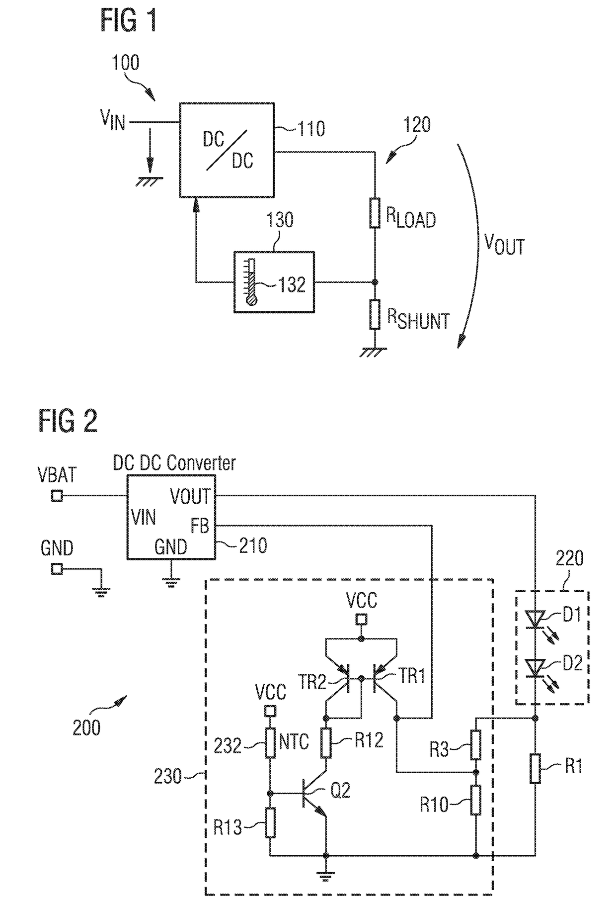
[0033]Similar references are used to describe similar concepts through several separate embodiments. For example, the references 100, 200 describe a power supply control device for a least one light source according to the invention in two separate embodiments.

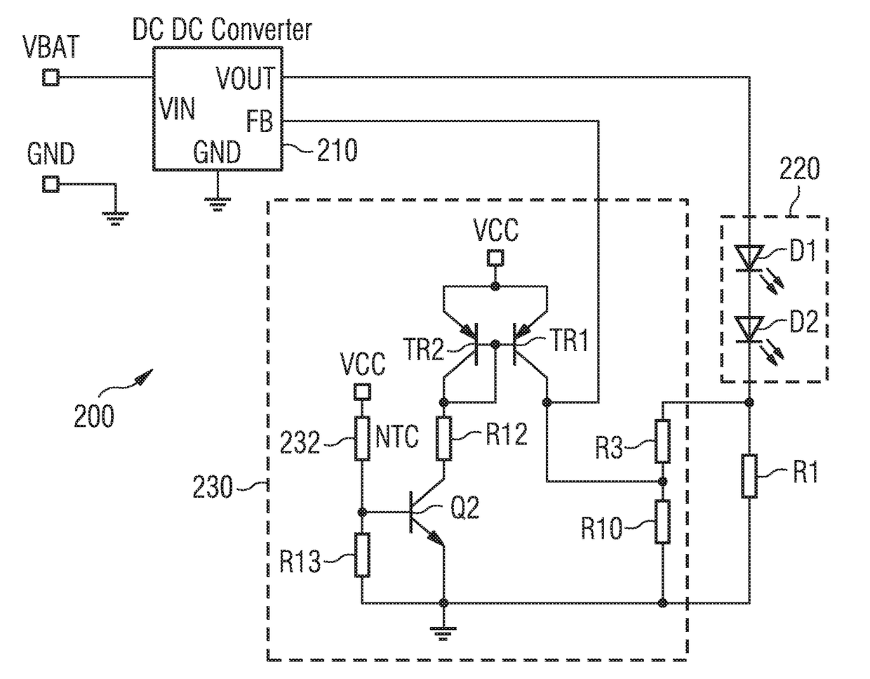
[0034]FIG. 1 schematically illustrates a power supply control device 100 according to the invention. The converter 110, which can be a buck or boost converter, or a combination of buck and boost converters, can convert an input direct voltage, VIN, provided by a non-illustrated source, into an output direct voltage VOUT. The converter 110 can provide a current with a fixed target intensity. A load circuit 120, illustrated for example by a resistor RLOAD, is powered using the converter 110. The load circuit 120 comprises at least one, preferably several light sources advantageously connected in series. These are advantageously light-emitting diodes (LED). The power supply control device 100 does not have a microcontroller eleme...


PUM


Abstract

A power supply control device and a method for controlling the power supply of light sources, preferably light-emitting diodes (LEDs). The power supply device allows the thermal management of LEDs without requiring the use of a programmable DC-to-DC converter, but by systematically adjusting an automatic control value for the DC-to-DC converter used.

Description

CROSS-REFERENCE TO RELATED APPLICATIONS[0001]This application is the U.S. National Phase application of PCT Application No. PCT / EP2015 / 062267 filed Jun. 2, 2015, which claims priority to the French application 1455036 filed on Jun. 3, 2014, which applications are incorporated herein by reference and made a part hereof.FIELD OF THE INVENTION[0002]The invention relates to the field of the power supply for light sources. In particular, the invention relates to a thermal management and power supply control system and method for light sources, more precisely light-emitting diodes (LEDs). The invention also relates to a light device for a motor vehicle.DESCRIPTION OF THE RELATED ART[0003]A light-emitting diode (LED) is an electronic component which can emit light when an electric current passes therethrough. The light intensity emitted by an LED is generally dependent upon the intensity of the electric current which passes therethrough. Among other things, a LED is characterized by a curr...

Claims


Application Information

Patent Timeline
Patent Type & Authority Applications(United States)
IPC IPC(8): H05B33/08B60Q1/26H05B44/00
CPCH05B33/0854B60Q1/26H05B33/089H05B45/50H05B45/3725H05B45/18H05B45/10H05B45/56
Inventor KRICK, SEBASTIAN
Owner VALEO VISION SA
Learn More