Input/output device and driving method thereof
a technology of input/output device and driving method, which is applied in the direction of counting objects on conveyors, television systems, instruments, etc., can solve the problems of insufficient reduce the quality of input/output image, and increase the switching speed of input/output image, reduce the quality of input/output image, and reduce the effect of flicker in input/output imag
- Summary
- Abstract
- Description
- Claims
- Application Information
AI Technical Summary
Benefits of technology
Problems solved by technology
Method used
Image
Examples
embodiment 1
[0029]In this embodiment, an example of an input / output device that can output data by displaying an image and can input data by using incident light is described.
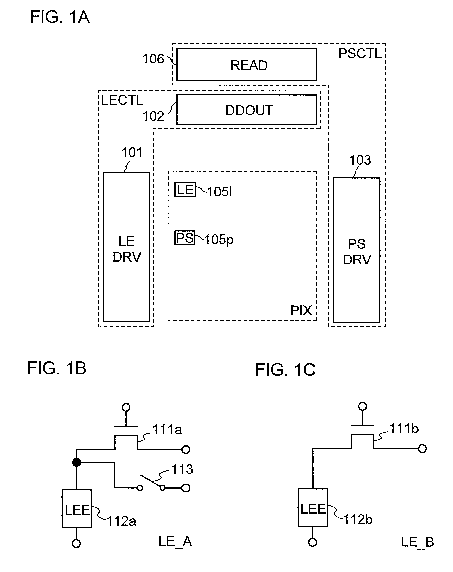
[0030]An example of the input / output device in this embodiment will be described with reference to FIGS. 1A and 1B.
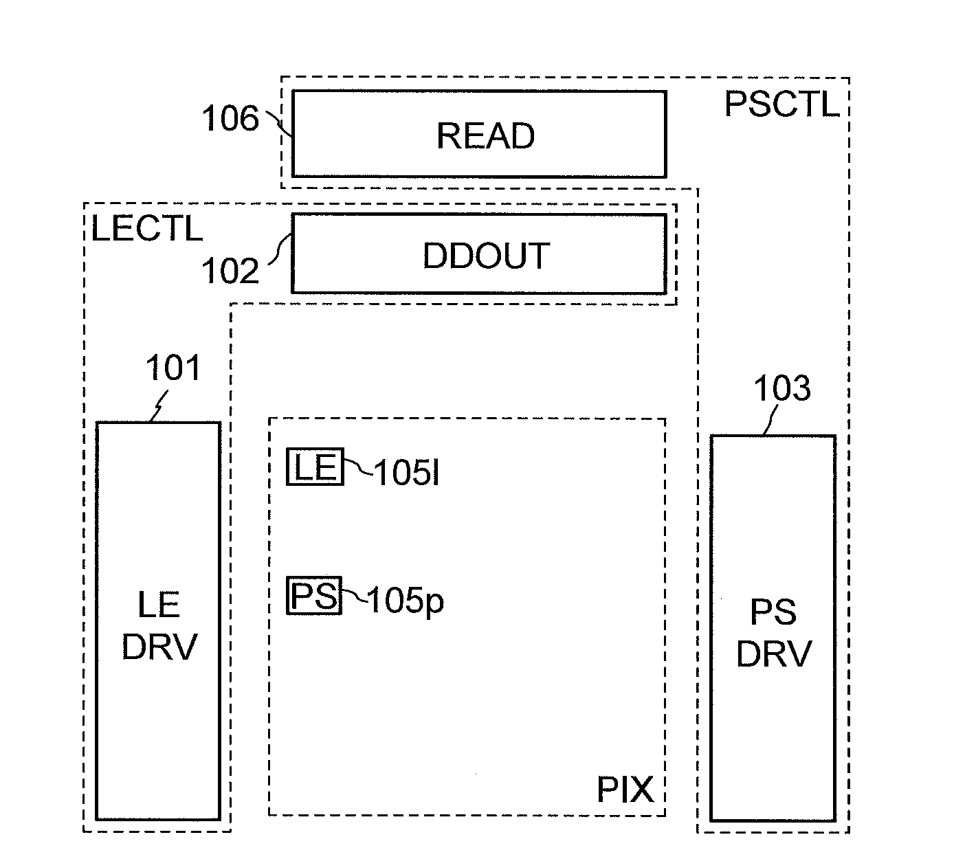
[0031]First, the structural example of the input / output device of this embodiment will be described with reference to FIG. 1A. FIG. 1A is a schematic diagram illustrating the structural example of the input / output device in this embodiment.
[0032]The input / output device in FIG. 1A includes a light emission controller LECTL, a photodetection controller PSCTL, and a pixel area PIX.
[0033]The light emission controller LECTL is a part controlling light emitting operation in the input / output device.
[0034]The photodetection controller PSCTL is a part controlling photodetection operation in the input / output device.
[0035]The pixel area PIX is a part inputting and outputting data by performing the light emitting operatio...
embodiment 2
[0116]In this embodiment, examples of the light emission circuit in one example of the input / output device of Embodiment 1 are described.
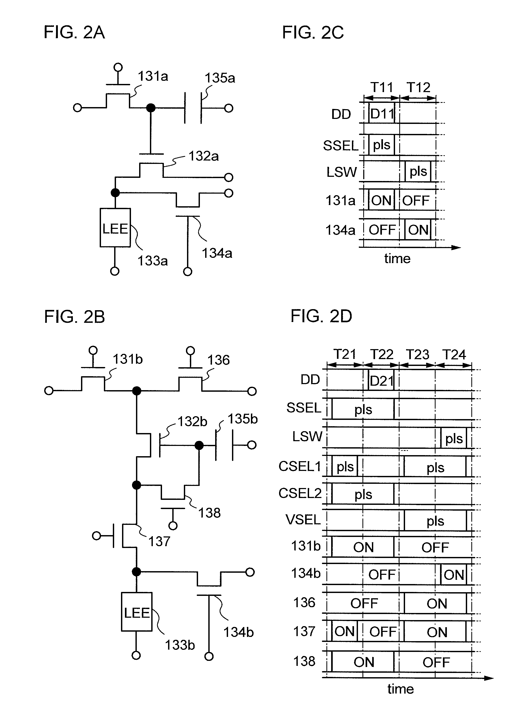
[0117]Examples of the light emission circuit in this embodiment will be described with reference to FIGS. 2A to 2D.
[0118]First, examples of the configuration of the light emission circuit in this embodiment will be described with reference to FIGS. 2A and 2B. FIGS. 2A and 2B illustrate examples of the configuration of the light emission circuit in this embodiment.
[0119]The light emission circuit in FIG. 2A includes a transistor 131a, a transistor 132a, a light emitting element (also called an LEE) 133a, a transistor 134a, and a capacitor 135a.
[0120]In the light emission circuit in FIG. 2A, the transistors 131a, 132a, and 134a are field-effect transistors.
[0121]Note that, in the input / output device, a capacitor includes a first capacitor electrode, a second capacitor electrode, and a dielectric layer overlapping with the first capacitor electrode a...
embodiment 3
[0174]In this embodiment, examples of the photodetection circuit in the input / output device of the above embodiment are described.
[0175]Examples of the photodetection circuit in this embodiment will be described with reference to FIGS. 3A to 3F. FIGS. 3A to 3F illustrate the examples of the photodetection circuit of this embodiment.
[0176]First, examples of the configuration of the photodetection circuit of this embodiment will be described with reference to FIGS. 3A to 3C. FIGS. 3A to 3C illustrate the examples of the configuration of the photodetection circuit of this embodiment.
[0177]The photodetection circuit illustrated in FIG. 3A includes a photoelectric transducer (PCE) 151a, a transistor 152a, and a transistor 153a.
[0178]Note that in the photodetection circuit illustrated in FIG. 3A, the transistor 152a and the transistor 153a are field-effect transistors.
[0179]A photodetection reset signal (also called a signal PRST) is input to the first current terminal of the photoelectr...
PUM
 Abstract
Description
Claims
Application Information
 - R&D
- Intellectual Property
- Life Sciences
- Materials
- Tech Scout
- Unparalleled Data Quality
- Higher Quality Content
- 60% Fewer Hallucinations
Browse by: Latest US Patents, China's latest patents, Technical Efficacy Thesaurus, Application Domain, Technology Topic, Popular Technical Reports.
© 2025 PatSnap. All rights reserved.Legal|Privacy policy|Modern Slavery Act Transparency Statement|Sitemap|About US| Contact US: help@patsnap.com


