Swimming pool vacuum relief safety valve

Inactive Publication Date: 2006-09-14
HAMZA HASSAN H
View PDF19 Cites 17 Cited by
  • Summary
  • Abstract
  • Description
  • Claims
  • Application Information

AI Technical Summary

Benefits of technology

[0009] The present invention resides in a vacuum relief safety valve for a swimming pool or spa pump. The safety valve generally comprises a housing defining an inner chamber and attached to the swimming pool or spa pump, or a suction-side pipe of

Problems solved by technology

Such vacuum forces have become so excessive that there have been cases of disembowelment.
When the suction inlet is located at or more adjacent to the bottom of a pool, the user can thus be submerged with the risk of drowning or other grievous injury.
However, these devices are fairly complex and expensive to produce.
Moreover, these approaches are only acceptable for new pool construction, and are not capable of being incorporated as a retrofit into existing pools and spas.
However, this approach also presents many drawbacks.
First, such piping is typically submerged below the ground and often encased in or otherwise positioned below concrete.
Thus, access to the pipes is not readily obtained unless the safety valve is incorporated into the system when the swimming

Method used


Image

  • Swimming pool vacuum relief safety valve
  • Swimming pool vacuum relief safety valve
  • Swimming pool vacuum relief safety valve

Examples


Embodiment Construction

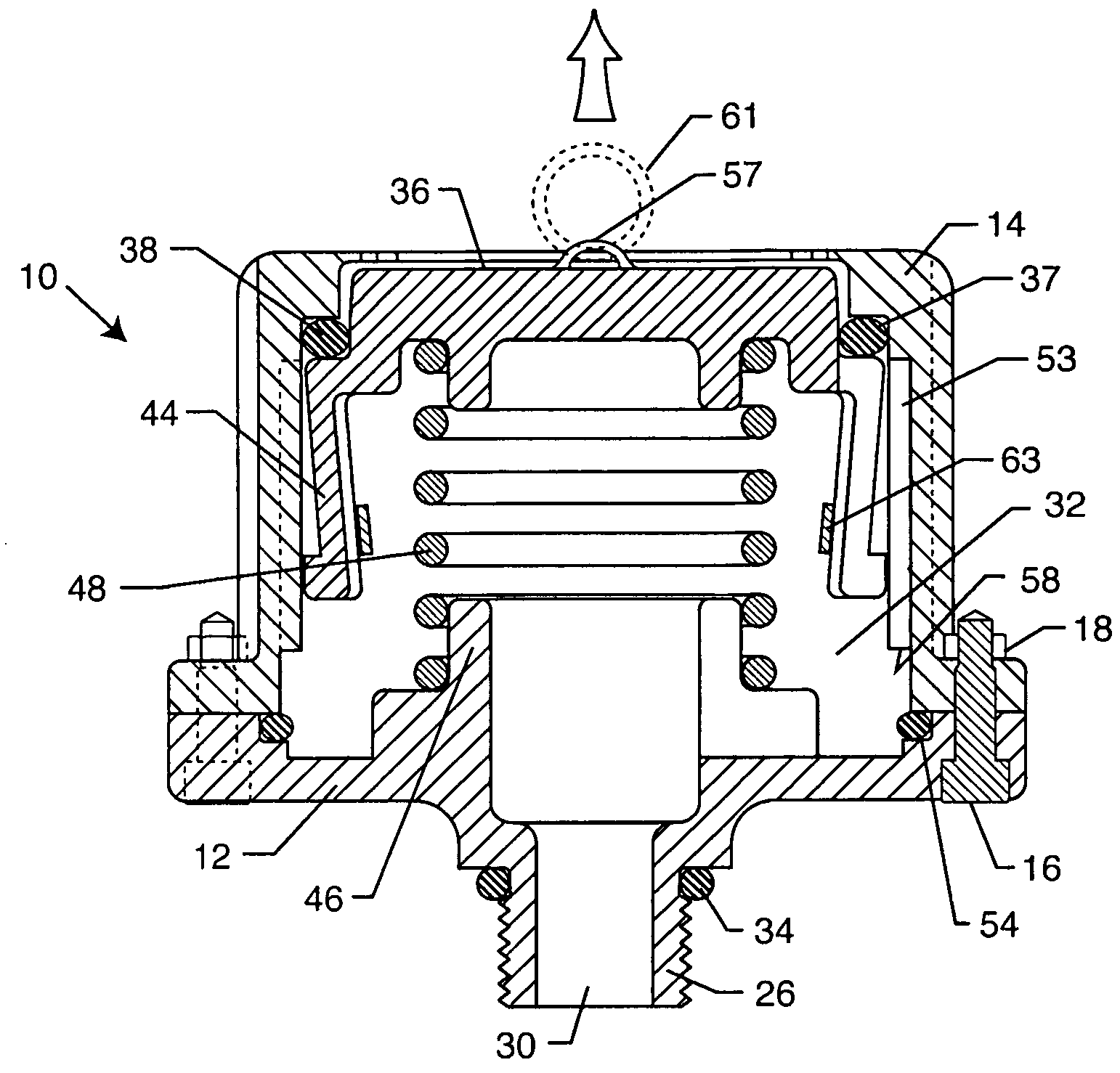
[0030] As shown in the accompanying drawings for purpose of illustration, the present invention resides in a vacuum relief safety valve for a swimming pool or spa pump which is designed to open and introduce ambient air into the pump such that it loses its prime when a vacuum level is exceeded caused by obstruction of a swimming pool drain. When the terminology “pool” or “spa” is used herein, it includes swimming pools, spas, ponds, lakes, etc., especially when the aforementioned have recreational applications. The term “drain” or “inlet” is used throughout the specification and can include one or more inlets or drains of various types. The present invention is particularly suited for residential pools, spas and hot tubs.

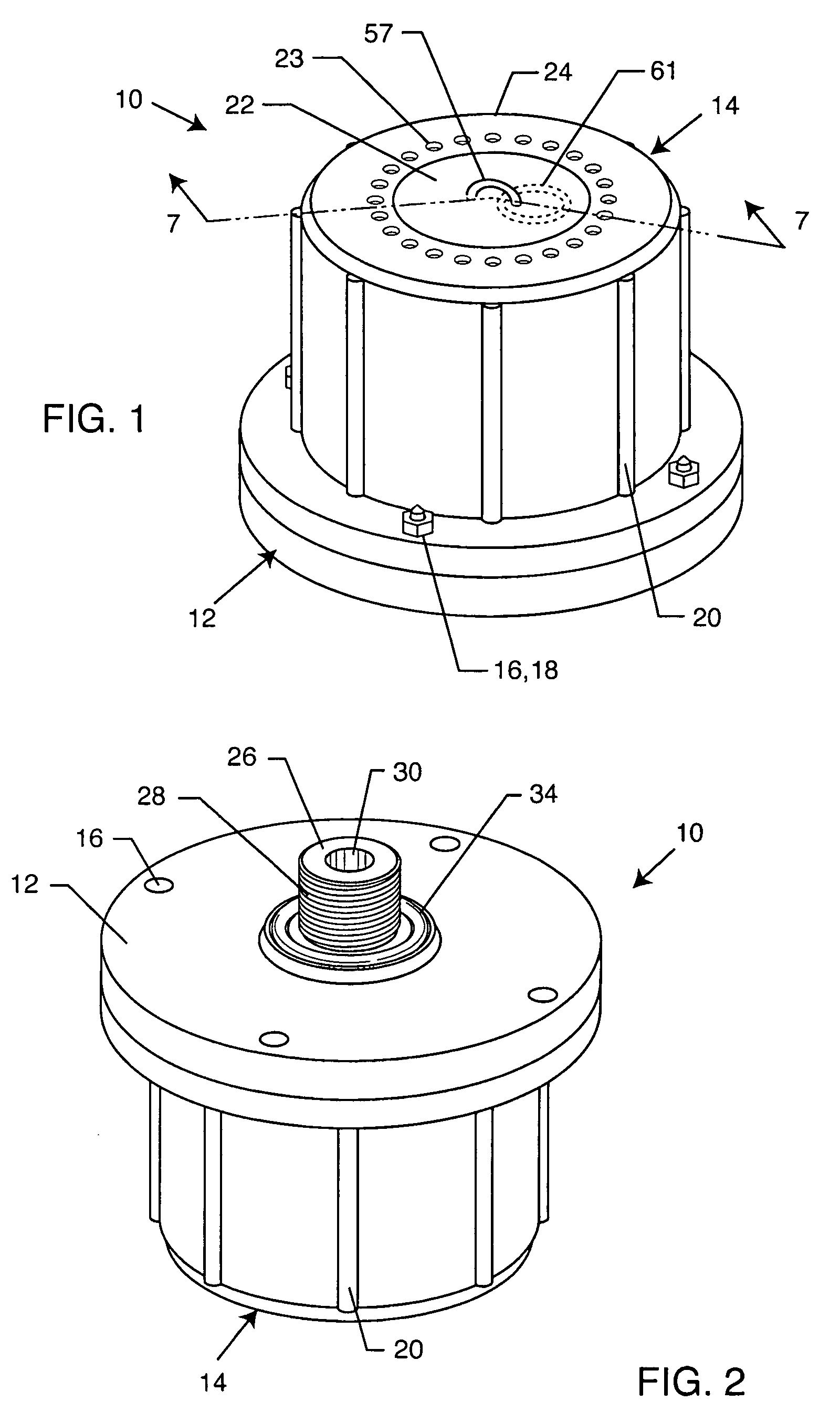
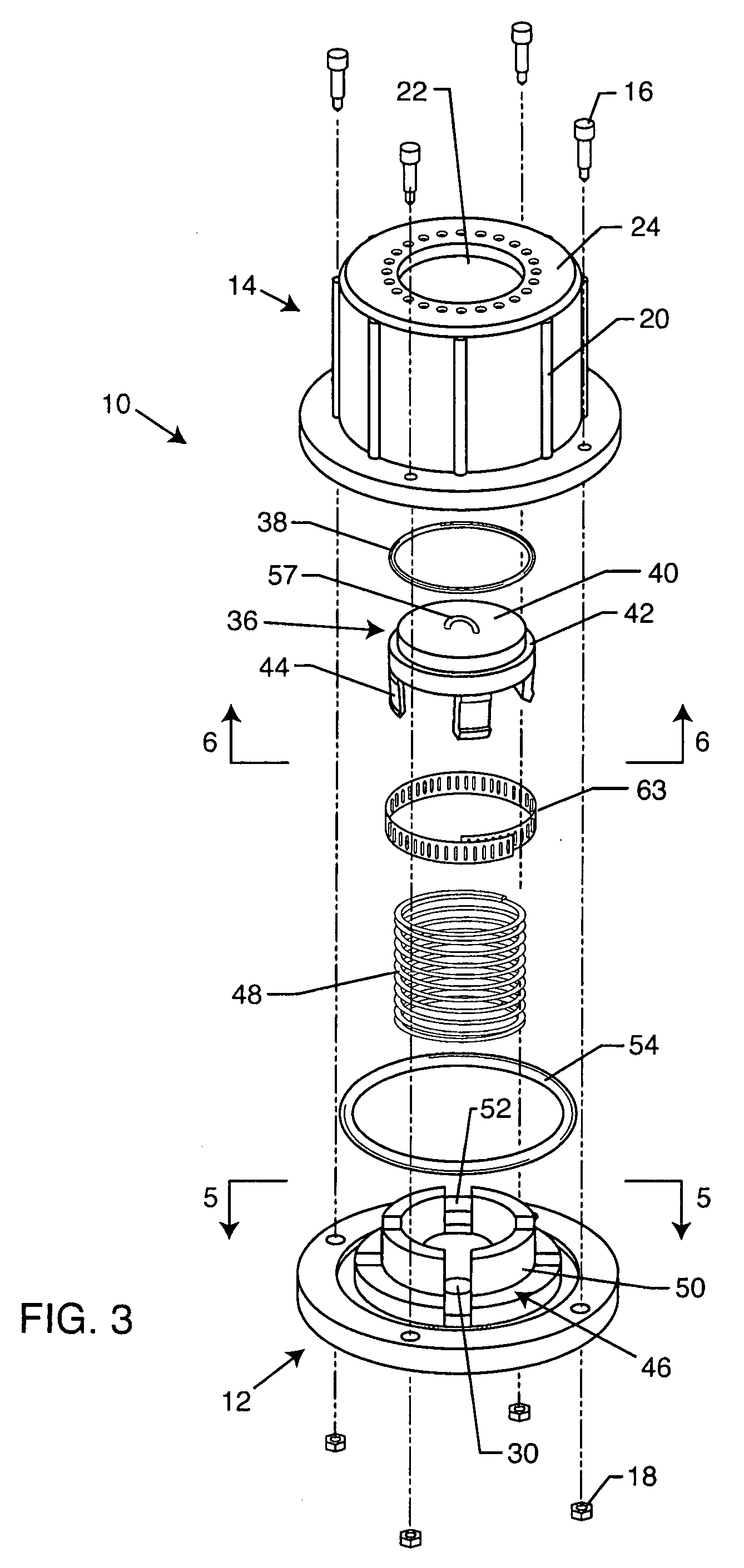
[0031] With reference now to FIGS. 1-4, a vacuum relief safety valve 10 embodying the present invention is shown. The safety valve 10 typically includes a base plate 12 and an upper cap 14 which are attached to one another, such as by the illustrated bolts and nuts...


PUM


Abstract

A vacuum relief safety valve includes a housing defining an inner chamber and attached to the suction-side of the swimming pool or spa pump. An air inlet aperture is formed in the housing so as to be open to ambient air. A sealing element is disposed within the housing and biased against the air inlet aperture by a spring so as to effectively seal the inner chamber of the housing from ambient air. When a maximum allowed vacuum level within the pump is exceeded, such as when a swimming pool drain is obstructed, the sealing element moves into the inner chamber and opens the air inlet aperture causing the pump to rapidly lose its prime and enabling removal of the entrapment.

Description

BACKGROUND OF THE INVENTION [0001] The present invention generally relates to vacuum relief valves. More particularly, the present invention relates to a vacuum relief safety valve for use in swimming pools, spas and the like which causes the pump to lose its prime if a pre-determined vacuum level is reached in the pump system, such as when an object obstructs the pool's drain. [0002] To maximize enjoyment and maintain proper sanitary conditions, swimming pools must be constantly cleaned of debris, dirt and other contaminants. Pools of various types are known to have one or more suction inlets where pool water is sucked along the line via a pump to filtration, aeration, chemical treatment and other type of equipment prior to being returned to the pool via one or more return outlets. [0003] In more recent pool designs, some of the suction inlets are positioned in the bottom or lower region of the pool. Very recently developed pool systems, known as in-floor cleaning systems, have one...

Claims


Application Information

Patent Timeline
IPC IPC(8): F16K17/04
CPCE04H4/12F04B49/022F04D15/0218F16K24/06A61H33/6073A61H2201/0173Y10T137/7734Y10T137/785Y10T137/7897
Inventor HAMZA, HASSAN H.
Owner HAMZA HASSAN H
Why Eureka
Try Eureka