Electric push-button switch

a push-button switch and push-button technology, applied in the direction of electric apparatus, legends, roads, etc., can solve the problems of inconvenient solution, inconvenient design, and increased structural space, and achieve the effect of fewer components and saving costs

Inactive Publication Date: 2006-09-14
TRW AUTOMOTIVE ELECTRONICS & COMPONENTS GMBH & CO KG
View PDF5 Cites 13 Cited by
  • Summary
  • Abstract
  • Description
  • Claims
  • Application Information

AI Technical Summary

Benefits of technology

[0007] According to the preferred embodiment of the invention, the light conducting section comprises a light conductor, and a switching mat is arranged over the second light source, a form fit existing between the light conductor and the switching mat. This construction makes possible a pleasant ‘feel’ to the switch upon actuating the light switch and makes it possible for the light of the second light source to enter through the switching mat into the light conductor, free of stray light.
[0008] In this context, a construction in which the light conductor extends into a bore in the switching mat is particularly advantageous. Thereby, the function of the switching mat is not impaired through a movement of the light conductor in the actuating direction.
[0009] The construction of the light conductor as a light block which extends from the bore of the switching mat up to the push-button, has the advantage that the separation of the light conducting section from the second light source to the light outlet area can be realized in a simple manner with few components.
[0010] In the preferred embodiment of the invention, provision is further made that the push-button switch comprises a reflector which divides an interior of the push-button switch into two lighting areas, the first lighting area restricting the outlet of the light of the first light source substantially to the transparent area, and the light conductor being guided in the second lighting area. The reflector thereby undertakes a dual function which makes it possible to make savings as regards components and structural space.

Problems solved by technology

This design is inefficient, however, for individual push-button switches and requires additional structural space.
In addition, this solution is not suitable for applications in which an external illumination of the push-button switches could be felt to be intrusive.

Method used


Image

  • Electric push-button switch
  • Electric push-button switch

Examples


Embodiment Construction

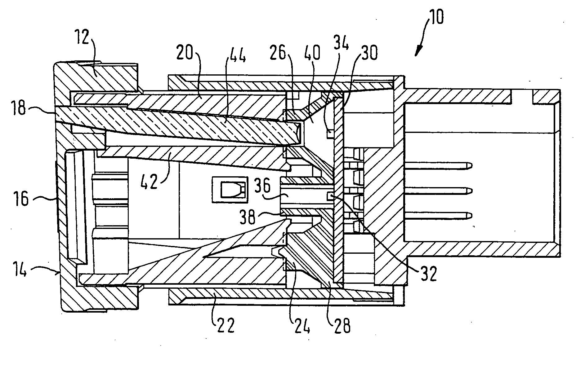
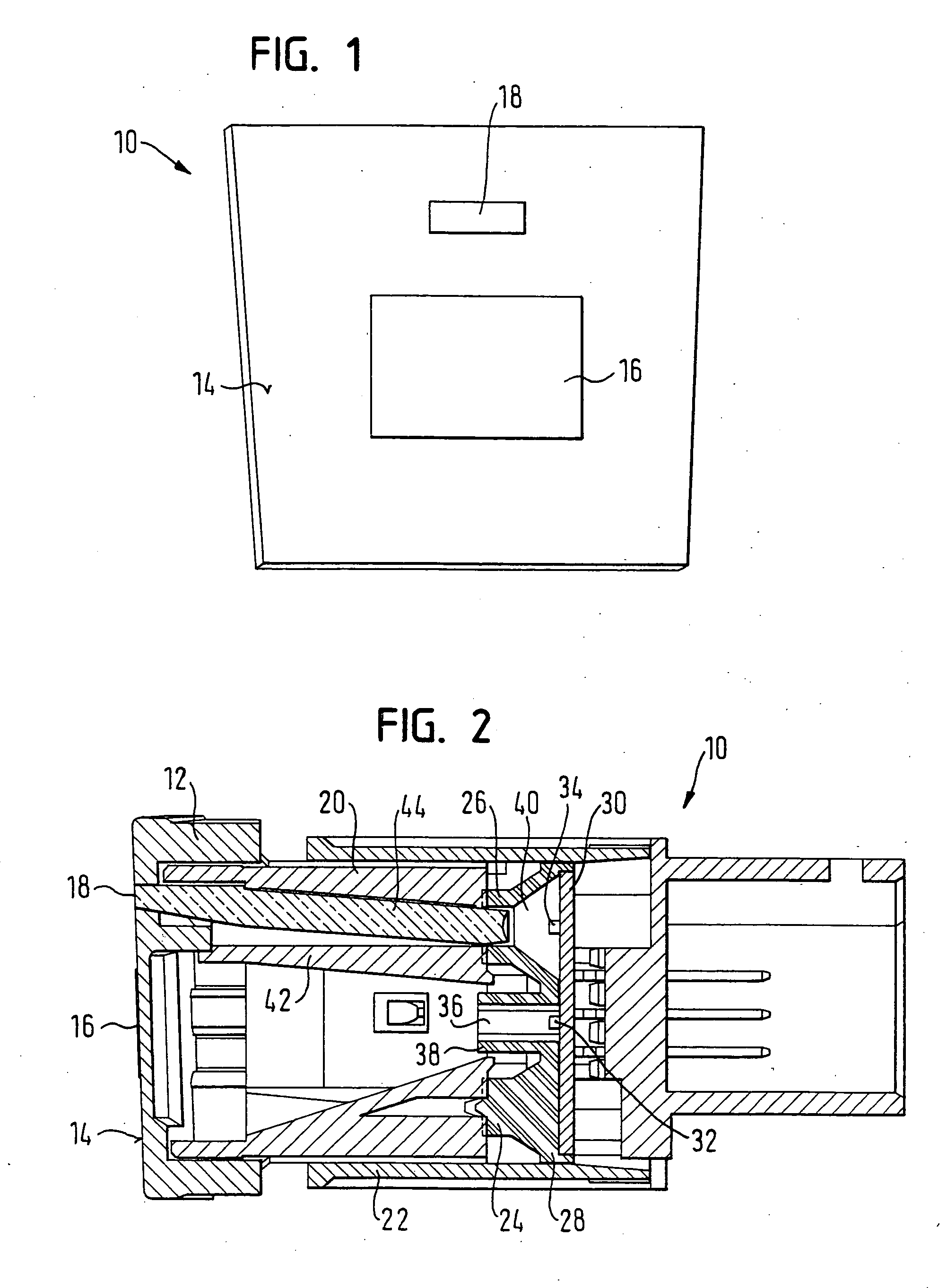
[0013] The switch 10 illustrated in FIGS. 1 and 2 is an electric push-button switch which is provided for operating a particular functional unit in a motor vehicle. The push-button switch 10 has a housing 22 and a movable push-button 12 with an operating surface 14. The operating surface 14 has a transparent symbol 16 which represents the functional unit or an actual function of the functional unit. A light outlet surface 18, by which the vehicle occupant is informed of the operating status of the functional unit, is situated over the symbol 16. The housing 22 and / or the push-button 12, which are constructed here in one piece respectively, can also be composed of several parts.

[0014] The structure of the push-button switch 10 can be seen in FIG. 2. The push-button 12 is securely connected with a reflector 20 which is guided in a housing 22 and sits on domes 24, 26 of a switching mat 28. The switching mat 28, in turn, lies on a printed circuit board 30. Upon an actuation of the push...


PUM


Abstract

An electric push-button switch (10) includes a housing (22), a push-button (12). The push-button switch (10) further includes a symbol lighting arrangement to illuminate a transparent region (16) of the push-button (12). The transparent region (16) symbolizes the functional unit to be operated by the push-button switch (10) or an actual function of the functional unit. The push-button switch (10) further includes a function lighting arrangement to indicate the operating status of the functional unit. The symbol lighting arrangement comprises a first light source (32), and the function lighting arrangement comprises a second light source (34) and an off-partitioned light conducting section to a light outlet area (18) which is integrated into the push-button (12). Both lighting arrangements are accommodated in a structural space defined by the housing (22).

Description

TECHNICAL FIELD [0001] The invention relates to an electric push-button switch, in particular an electric push-button switch in a motor vehicle to operate a functional unit. BACKGROUND OF THE INVENTION [0002] Push-button switches in motor vehicles are able to be found easily in the dark when a symbol on the operating surface of the push-button is illuminated by a symbol lighting arrangement. Generally, the symbol is illuminated when the headlights of the vehicle are switched on. With some push-button switches, it is efficient to inform the vehicle occupant of the current switching status of the push-button switch, e.g. as to whether a functional unit is switched on or off. An additional function lighting arrangement can be provided for this, having a outlet area in the push-button which is illuminated separately from the symbol lighting only as a function of the operating status of the functional unit which is to be operated. [0003] In EP-A-1 107 268 a push-button switch is shown, w...

Claims


Application Information

Patent Timeline
Patent Type & Authority Applications(United States)
IPC IPC(8): H01H9/00H01H9/18H01H13/02
CPCH01H9/182H01H13/023H01H2013/026H01H2219/062H01H2219/064H01H2231/026
Inventor OSTENDORF, JENSGIRKE, JUERGENFROHNE, HANS-JOACHIM
Owner TRW AUTOMOTIVE ELECTRONICS & COMPONENTS GMBH & CO KG
Why Eureka
Try Eureka