

Racket
a racket and sledge technology, applied in the field of rackets, can solve the problems of short range of contact between the string s and the grommet member, insufficient vibration of the string s, and unpleasant feeling of the player, and achieve the effect of reducing the movable length of the string and the sweet area, preventing unpleasant vibration, and facilitating the player to feel
Inactive Publication Date: 2010-04-06
SUMITOMO RUBBER IND LTD
View PDF7 Cites 15 Cited by
- Summary
- Abstract
- Description
- Claims
- Application Information
AI Technical Summary
Benefits of technology
The present invention provides a racket with improved repulsion for a ball and a sweet area for the player. The racket includes a string-stretching part with a double-tubular grommet mounted in a string hole. The double-tubular grommet has an inner and an outer tubular portion with a base portion integrally connected with the string-stretching part. The double-tubular grommet is made of a material with vibration-damping performance. The racket also has improved durability and operability. The invention solves the problem of unpleasant vibration and provides a better feeling for the player when hitting the ball.
Problems solved by technology
But it is conceivable that in the grommet member 4 of the patent document 1, the range of contact between the string S and the grommet member 4 is short, and the vibration of the string S is insufficiently damped.
Thus a player has an unpleasant feeling when the player hits a ball.
Further because the grommet member 6 and the belt-shaped member 7 are made of different materials, the string protection member 5 is assembled at a low operability and liable to be defectively mounted on the racket frame.
Method used
View moreImage
Smart ImageViewing Examples

Examples
example 1
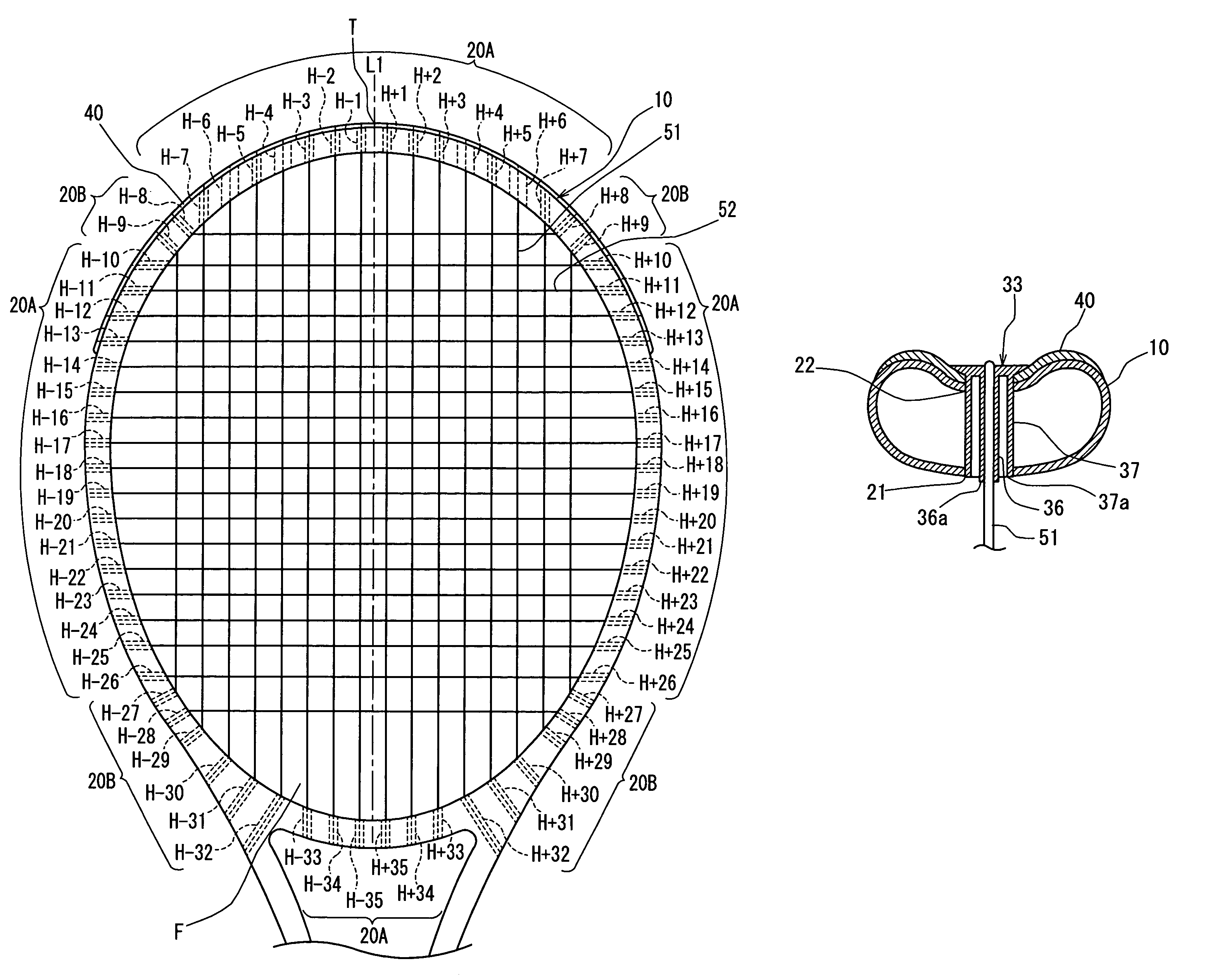
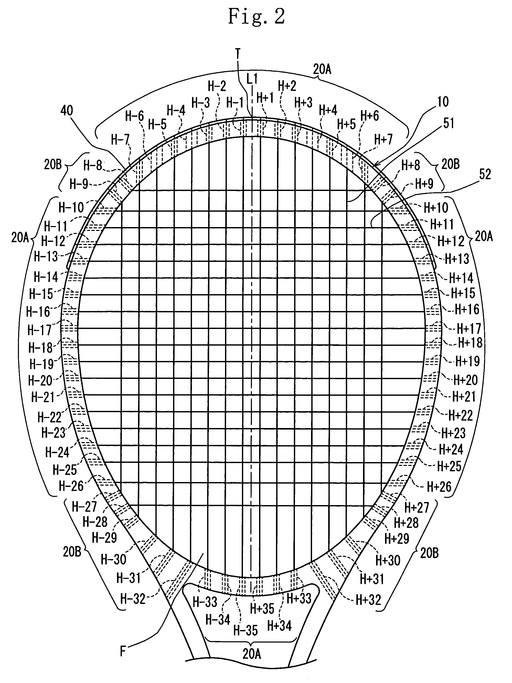
[0129]The racket frame of the example 1 had the same construction as that of the racket frame of the first embodiment. More specifically, the double-tubular grommets 33 were mounted in the string holes H+4, H+6, H−4, and H−6. The inward projected-side tip 36a of the inner tubular portion 36 was slightly projected inward beyond the inward open portion 21 of the string hole 20. The inward projected-side tip 37a of the outer tubular portion 37 was brought into contact with the inner peripheral surface of the inward open portion 21 of the string hole 20.
[0130]The product “PEBAX7033” (tan δ at −5° C.: 0.10, Shore D hardness: 69, material: polyether block amide copolymer) produced by ATOFINA Inc. was molded to form the double-tubular grommet 33.
Login to View More PUM
 Abstract
A racket including a string-stretching part for forming a ball-hitting face by tensionally mounting strings in string holes, formed through the string-stretching part, in which grommets are mounted respectively. As the grommets, a double-tubular grommet is mounted in at least one of the string holes. The double-tubular grommet is formed as an integrally molded article, including an inner tubular portion having a string insertion hole through which the string is inserted with the string in contact with the string insertion hole and pulled from an inward-end open portion thereof or an outward-end open portion thereof; an outer tubular portion fitted in the string hole formed through the string-stretching part with the outer tubular portion spaced at a certain interval from the inner tubular portion; and a base portion integrally connected with an outward-side end of the inner tubular portion and that of the outer tubular portion and disposed on a peripheral surface of the string-stretching part.
Description
[0001]This nonprovisional application claims priority under 35 U.S.C. §119(a) on Patent Application No(s). 2007-180656 filed in Japan on Jul. 10, 2007, the entire contents of which are hereby incorporated by reference.BACKGROUND OF THE INVENTION[0002]1. Field of the Invention[0003]The present invention relates to a racket for tennis and the like and more particularly to a racket having an improved grommet mounted in string holes formed through a string-stretching part to increase the sweet area of a ball-hitting face of a racket frame and improve the vibration-damping performance thereof.[0004]2. Description of the Related Art[0005]As shown in FIG. 8, in a conventional racket frame, string holes 2 are formed in penetration through a string-mounting part 1 constituted of a circular arc-shaped frame surrounding the ball-hitting face, with the string holes 2 disposed vertically to tangents to the string-stretching part 1. In this method, it is easy to use a drill in forming the string ...
Claims
Login to View More Application Information
Patent Timeline
 Patent Type & AuthorityPatents(United States)
IPC IPC(8): A63B49/00A63B49/022A63B49/028A63B51/10A63B60/54A63B102/02
CPCA63B49/002A63B2209/00A63B59/0092A63B49/007A63B49/022A63B49/028A63B60/54
InventorASHINO, TAKESHI
OwnerSUMITOMO RUBBER IND LTD