
Microjet actuators for the control of flow separation and distortion

a microjet actuator and actuator technology, applied in the direction of air-flow influencers, aircraft navigation control, vertical landing/take-off aircraft, etc., can solve the problems of degrading engine performance, flow separation is undesirable in many applications, and flow separation is a known problem

Inactive Publication Date: 2006-09-14
FLORIDA STATE UNIV RES FOUND INC
View PDF14 Cites 31 Cited by
  • Summary
  • Abstract
  • Description
  • Claims
  • Application Information

AI Technical Summary

Benefits of technology

[0011] The present invention comprises a system for controlling unwanted flow separation in a fluid flowing over a surface. The fluid can be compressible (such as air) or incompressible (such as water). One or more microjets are placed to feed auxiliary fluid into a region of suspected flow separation. If the separation is intermittent, sensors can be employed to detect its onset. Once separation is developing, the microjets are activated to inject a stream of fluid into the separation region. This injected fluid affects the flow and serves to control the flow separation.

Problems solved by technology

Flow separation is undesirable in many applications.
Flow separation is a known problem in such applications.
This variance produces flow separation in different locations at different times. A substantial flow separation can degrade the engine performance and even lead to compressor stall.

Method used


Image

  • Microjet actuators for the control of flow separation and distortion
  • Microjet actuators for the control of flow separation and distortion
  • Microjet actuators for the control of flow separation and distortion

Examples


Embodiment Construction

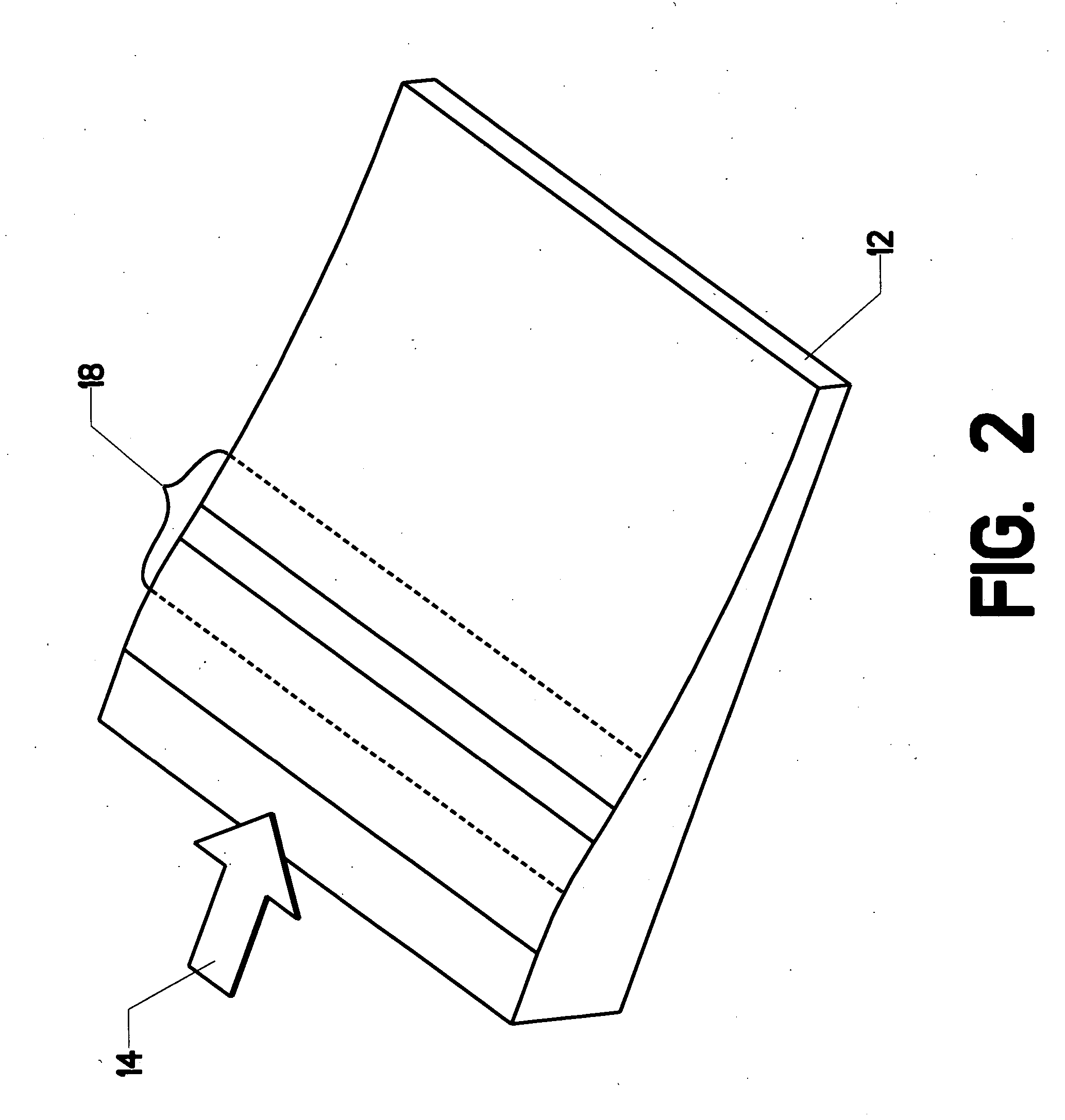
[0029] The present invention can be applied to flow control over many different types of surfaces. As an initial explanation, however, it is useful to describe its application to one particular type of simple surface. FIG. 2 shows an adverse pressure gradient ramp 12. If air flow 14 is directed over the ramp at an appropriate velocity, flow separation will occur in the region of high adverse pressure gradient 18. Air flowing over this geometry produces an adverse pressure gradient. The pressure coefficient is defined by the following expression: Cp=(Psurface-P∞)0.5⁢ρ·U∞2

In this expression, ρ is the density of the fluid and U∞ is the undisturbed flow velocity, well away from the ramp.

[0030]FIG. 3 is a detailed elevation view of the ramp surface in the region of high adverse pressure gradient 18. The approaching flow is represented by velocity vectors 20. Those skilled in the art will be familiar with this type of depiction. The reader will observe that the flow in the vicinity of ...


PUM


Abstract

A system for controlling unwanted flow separation. One or more microjets are placed to feed auxiliary fluid into a region of suspected flow separation. If the separation is intermittent, sensors can be employed to detect its onset. Once separation is developing, the microjets are activated to inject a stream of fluid into the separation region. This injected fluid affects the flow and serves to control the flow separation. A steady-state embodiment can be used to continuously fluid. On the other hand, sensors and a rapidly reactive control circuit can be used to inject fluid only when it is needed to inhibit flow separation. The sensors and control circuit can operate off of simple pressure gradient detection or predictive algorithms that anticipate when flow separation will occur.

Description

CROSS-REFERENCES TO RELATED APPLICATIONS [0001] This application is a non-provisional application claiming the benefit of an earlier-filed provisional application pursuant to the provisions of 37 C.F.R. §1.53. The earlier-filed provisional application listed the same inventor. It was filed on Jan. 21, 2005 and was assigned application Ser. No. 60 / 646,951.STATEMENT REGARDING FEDERALLY SPONSORED RESEARCH OR DEVELOPMENT [0002] This invention involves federally sponsored research. The sponsoring agency is the National. Aeronautics and Space Administration. MICROFICHE APPENDIX [0003] Not Applicable BACKGROUND OF THE INVENTION [0004] 1. Field of the Invention [0005] This invention relates to the field of flow control in a fluid. More specifically, the invention comprises the use of properly placed microjets to control flow separation and or recirculation over a given surface. [0006] 2. Description of the Related Art [0007] Flow separation is defined as the detachment of a flowing fluid fr...

Claims


Application Information

Patent Timeline
Patent Type & Authority Applications(United States)
IPC IPC(8): B64C29/00
CPCB64C21/04F15D1/12Y02T50/166B64C2230/18Y02T50/10
Inventor ALVI, FARRUKH S.
Owner FLORIDA STATE UNIV RES FOUND INC
Learn More