Perpendicular magnetic recording head and method of manufacturing the same

a magnetic recording head and perpendicular technology, applied in the field of magnetic recording heads, can solve the problem of not being able to obtain superior coil peculiarities, and achieve the effects of preventing short circuits, high precision, and suppressing diffused reflection of ligh

Active Publication Date: 2006-09-14
TDK CORPARATION
View PDF6 Cites 2 Cited by
  • Summary
  • Abstract
  • Description
  • Claims
  • Application Information

AI Technical Summary

Benefits of technology

[0025] In the perpendicular magnetic recording head according to the aspect of the invention, since the bottom brim portion of the inclined surface of the second insulating layer is formed so as to be located in the flat surface of the first insulating layer, the inclined angle θ1 of the inclined surface of the first insulating layer with respect to the flat surface can be made to be smaller than the inclined angle θ2 of the inclined surface of the second insulating layer with respect to the flat surface. Therefore, when performing a patterning process of a resist pattern for forming the second insulating layer, it is possible to suppress the diffused reflection of the light from occurring due to the exposure at the time of exposing and developing the resist layer at the inclined surface formed in the second insulating layer.
[0026] Therefore, the second coil layer can be formed with high precision while preventing an abnormal shape from forming in the resist pattern for forming the second coil layer. As a result, an abnormal shape can be prevented from forming in the second coil layer, so that it is possible to prevent a short circuit from occurring. Therefore, the second coil layer having superior coil peculiarity can be obtained.
[0027] In addition, in the perpendicular magnetic recording head, the inclined surface is formed on the first insulating layer which is located between the first coil layer and the second coil layer, and a lateral region of the second coil layer extends downward along the inclined surface of the second insulating layer which is formed on the inclined surface. For this reason, the second coil layer can be electrically connected to the first coil layer through only the contact layers. Accordingly, an electrical resistance is minimally suppressed between the first coil layer and the second coil layer, which results in obtaining a superior coil peculiarity.
[0028] In addition, since the second coil layer is formed such that the lateral region thereof extends downward along the inclined surface of the first insulating layer, the second coil layer can be made to be close to the first coil layer in a vertical direction. As a result, the thickness of the contact layer can be decreased. Therefore, a resistance value of the entire coil layer can be decreased.
[0029] Further, in the method of manufacturing the perpendicular magnetic recording head according to another aspect, the first inclined surface is formed on the first insulating layer which is located between the first coil layer and the second coil layer. In addition, a lateral region of the second coil layer extends downward along the inclined surface of the second insulating layer which is formed on the inclined surface. For this reason, the second coil layer can be electrically connected to the first coil layer through only the contact layers. Accordingly, an electrical resistance is minimally suppressed between the first coil layer and the second coil layer, which results in obtaining a superior coil peculiarity.
[0030] Furthermore, since the second coil layer is formed such that the lateral region thereof extends downward along the inclined surface of the first insulating layer, the second coil layer can be made to be close to the first coil layer in a vertical direction. As a result, the thickness of the contact layer can be decreased. Therefore, a resistance value of the entire coil layer can be decreased.

Problems solved by technology

As a result, it is not possible to obtain a superior coil peculiarity.

Method used


Image

  • Perpendicular magnetic recording head and method of manufacturing the same
  • Perpendicular magnetic recording head and method of manufacturing the same
  • Perpendicular magnetic recording head and method of manufacturing the same

Examples


Embodiment Construction

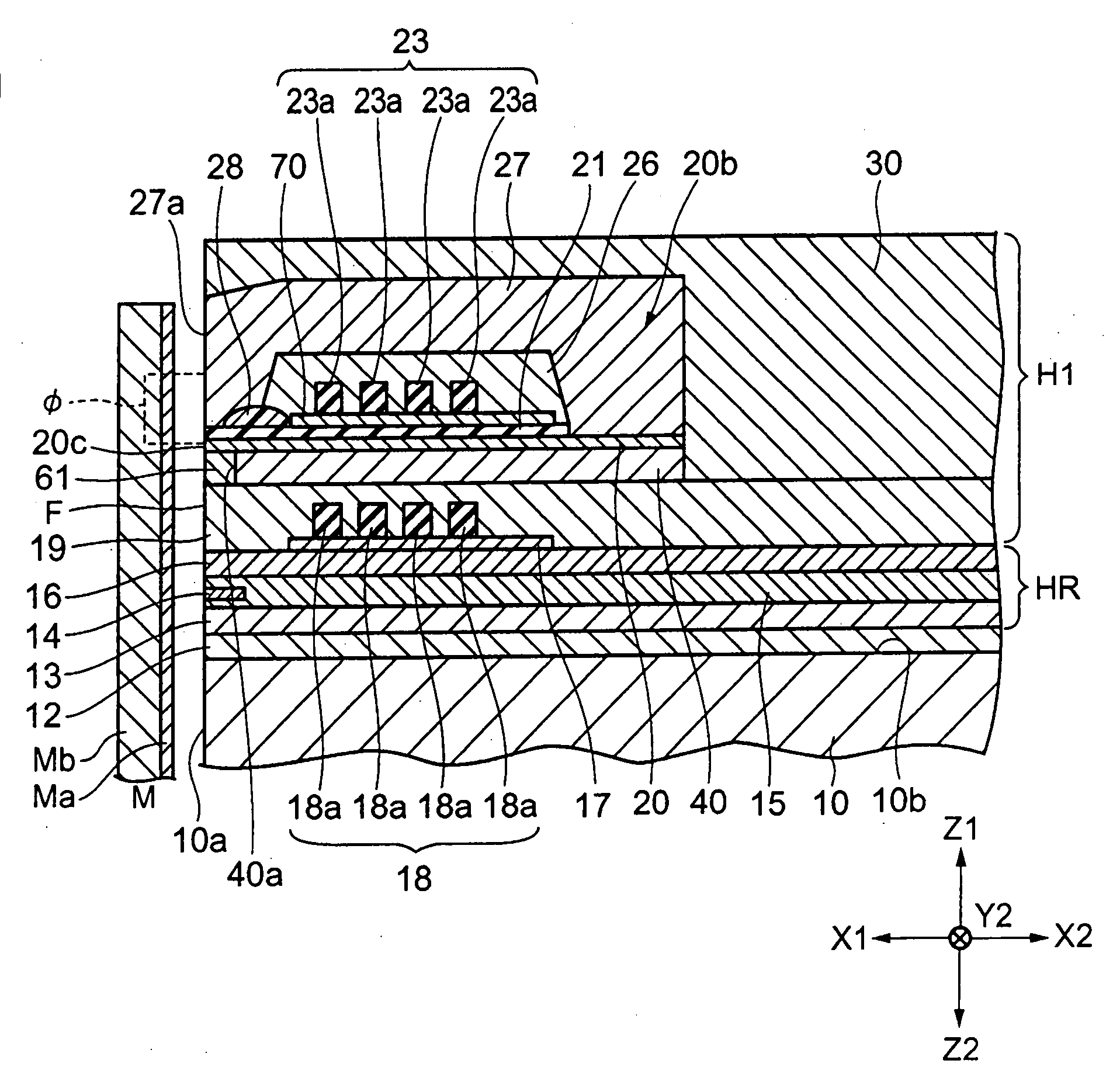
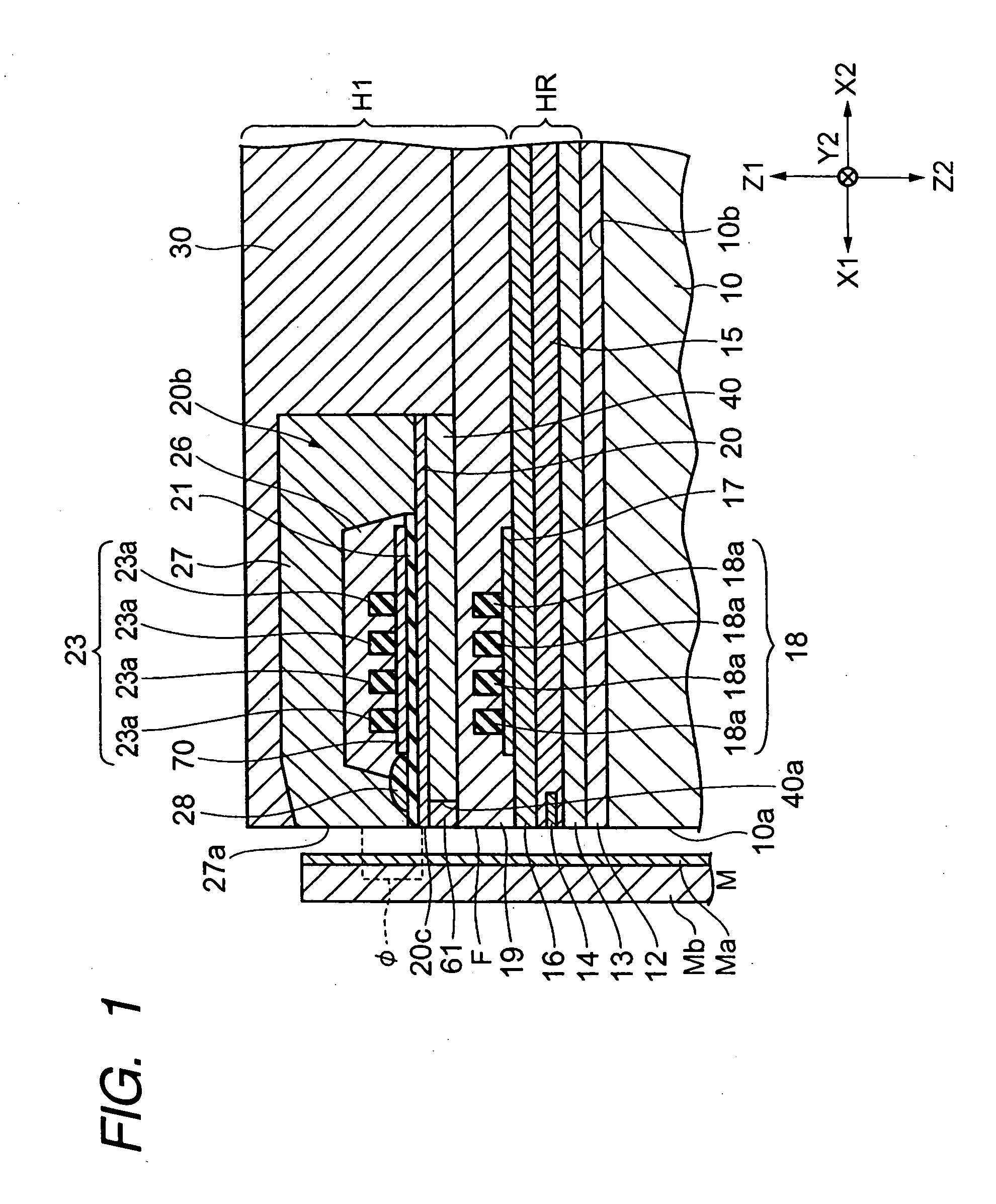
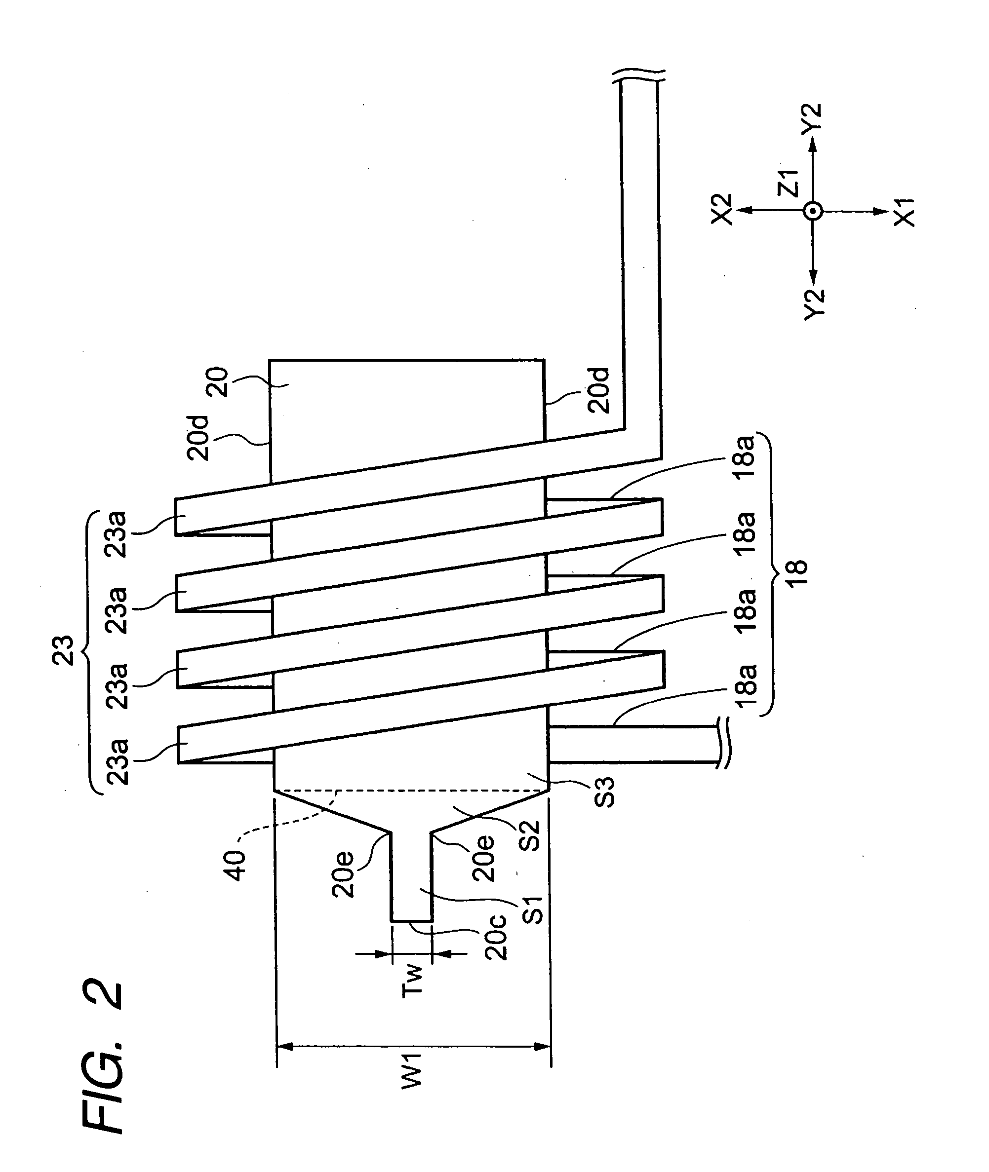
[0049]FIG. 1 is a partial longitudinal cross-sectional view illustrating a perpendicular magnetic recording head according to an embodiment of the invention, FIG. 2 is a partial plan view illustrating a perpendicular magnetic recording head illustrated in FIG. 1; and FIG. 3 is a partial front view illustrating a perpendicular magnetic recording head illustrated in FIG. 1 as viewed from a recording medium facing surface F.

[0050] Hereinafter, a direction of X1-X2 in the respective drawings is referred to as a track width direction, and a direction of Y2 in the respective drawings is referred to as a heightwise direction. Further, a recording medium facing surface F is formed in a direction parallel to a plane which is formed in the track width direction (a direction of X1-X2 in the drawing) and a film thickness direction (a direction of Z1-Z2 in the drawing).

[0051] In a perpendicular magnetic recording head H1 shown in FIG. 1, a perpendicular magnetic field is applied to a recording...


PUM

PropertyMeasurementUnit
inclined angle θ1aaaaaaaaaa
widthaaaaaaaaaa
electricallyaaaaaaaaaa

Abstract

A perpendicular magnetic recording head is provided that has a first coil layer is electrically connected to a second coil layer through contact layers. A laminator has a main magnetic pole layer and a gap layer which are formed between the first and second coil layers and above the contact layers. At both sides of the laminator, first insulating layers are formed. A second insulating layer is formed from a top surface of the laminator to top surfaces of the first insulating layers. An inclined surface is formed in each of the first insulating layers, and in the second insulating layer, the inclined surface is formed on the inclined surface of the first insulating layer. A lateral region of the second coil layer extends downward along the inclined surfaces of the second insulating layer, and an inclined angle on the inclined surface of the first insulating layer is larger than an inclined angle on the inclined surface of the second insulating layer.

Description

BACKGROUND OF THE INVENTION [0001] 1. Field of the Invention [0002] The present invention relates to a magnetic head, and more particularly, to a perpendicular magnetic recording head which is capable of effectively preventing a short circuit from occurring between coil layers of a recording head and obtaining an excellent coil peculiarity and a method of manufacturing the same. [0003] 2. Description of the Related Art [0004] Each of FIG. 21 of JP-A-2002-170205 (Pub. No.: US 2002 / 0089783 A1) and FIG. 1 of JP-A-05-242429 discloses a configuration of a coil layer wound in a solenoid shape around a magnetic pole layer or a core layer which forms an inductive head (recording head). [0005] In order to effectively use a three-dimensional space around the core layer, the coil layer is preferably wound in a helical shape. Therefore, it is possible to achieve a small-sized inductive head with superior magnetization efficiency. [0006] In each of JP-A-2002-170205 and JP-A-05-242429, a front vi...

Claims


Application Information

Patent Timeline
Patent Type & Authority Applications(United States)
IPC IPC(8): G11B5/147
CPCG11B5/1278G11B5/312G11B5/3143G11B5/3163
Inventor KOBAYASHI, KIYOSHI
Owner TDK CORPARATION
Why Eureka
Try Eureka