Pool cleaner

a technology for cleaning and pool water, applied in the field of pool cleaners, can solve the problems of wasting energy of bypassed flow, reducing the service life of pool cleaners, so as to achieve the shallowness at which they will operate and the limitations of their ability

Inactive Publication Date: 2006-09-21
ZODIAC POOL CARE +1
View PDF37 Cites 29 Cited by
  • Summary
  • Abstract
  • Description
  • Claims
  • Application Information

AI Technical Summary

Benefits of technology

[0017] Portions of the spheroidal surfaces of the segments may have brush like formations, e.g. bristles, on them, to give a brushing effect.
[0020] This counter intuitive approach results in a less stable device under water, which is tolerable by virtue of the spheroidal shape of the cleaner of this invention. The lower stability results in more random movement over the pool surface which in turn gives the advantage, as mentioned, of less tendency for the cleaner to repeatedly miss some areas, leaving them uncleaned.
[0021] A feature of this invention, whether the floats are used, or not, is that the centre of gravity is made closer to the axis of rotation of the cleaner than is appropriate in cleaners of conventional design. This feature again reduces stability and as a result brings the beneficial advantage of greater randomness than is achieved in conventional cleaners. This is possible simply for the reason already stated, that spheroidal shape gives the advantage that the cleaner can not “capsize” into a position in which it can no longer move, like a conventional vehicle.
[0024] Preferably the passage is given a direction, at least near the mouth of the passage, which has a tangential component as well as a radial component. In other words, the venturi passage, at least near its mouth, is preferably not normal (at right angles) to the spheroidal outer surfaces of the cleaner. The passage is oriented so that the mouth is directed in the direction in which the cleaner moves. This gives a degree of scooping action, helpful to lifting debris from the pool surfaces. Jets which provide the suction action in the suction passage, given this tangential component of direction, also assists in the forward impulsion of the cleaner, by jet reaction forces.

Problems solved by technology

Again, whereas suction side pool cleaners have few moving parts, the cleaner moving over the pool surfaces under impulsion of intermittent water flow caused by an oscillating tongue, or a suction tube whose wall collapses intermittently, for example, certain push side pool cleaners of the art have the disadvantage that they are moved by means of a water turbine driving the wheels through a drive train consisting of many gears and shafts.
Although push side pool cleaners do have potential for less interference with the desirable randomness of movement over the pool surfaces, due to a smaller diameter hose being acceptable, than suction side cleaners, much of this potential advantage is lost by the wheeled drive of these cleaners of the push side cleaner art which tend to provide straight line travel.
A disadvantage of this arrangement of the art is that the energy of the bypassed flow is discarded.
Finally, all present pool cleaners have limitations as to the shallowness at which they will operate and as to their ability to negotiate formations like stairs in pools without becoming stuck in one position.

Method used


Image

  • Pool cleaner
  • Pool cleaner
  • Pool cleaner

Examples


Embodiment Construction

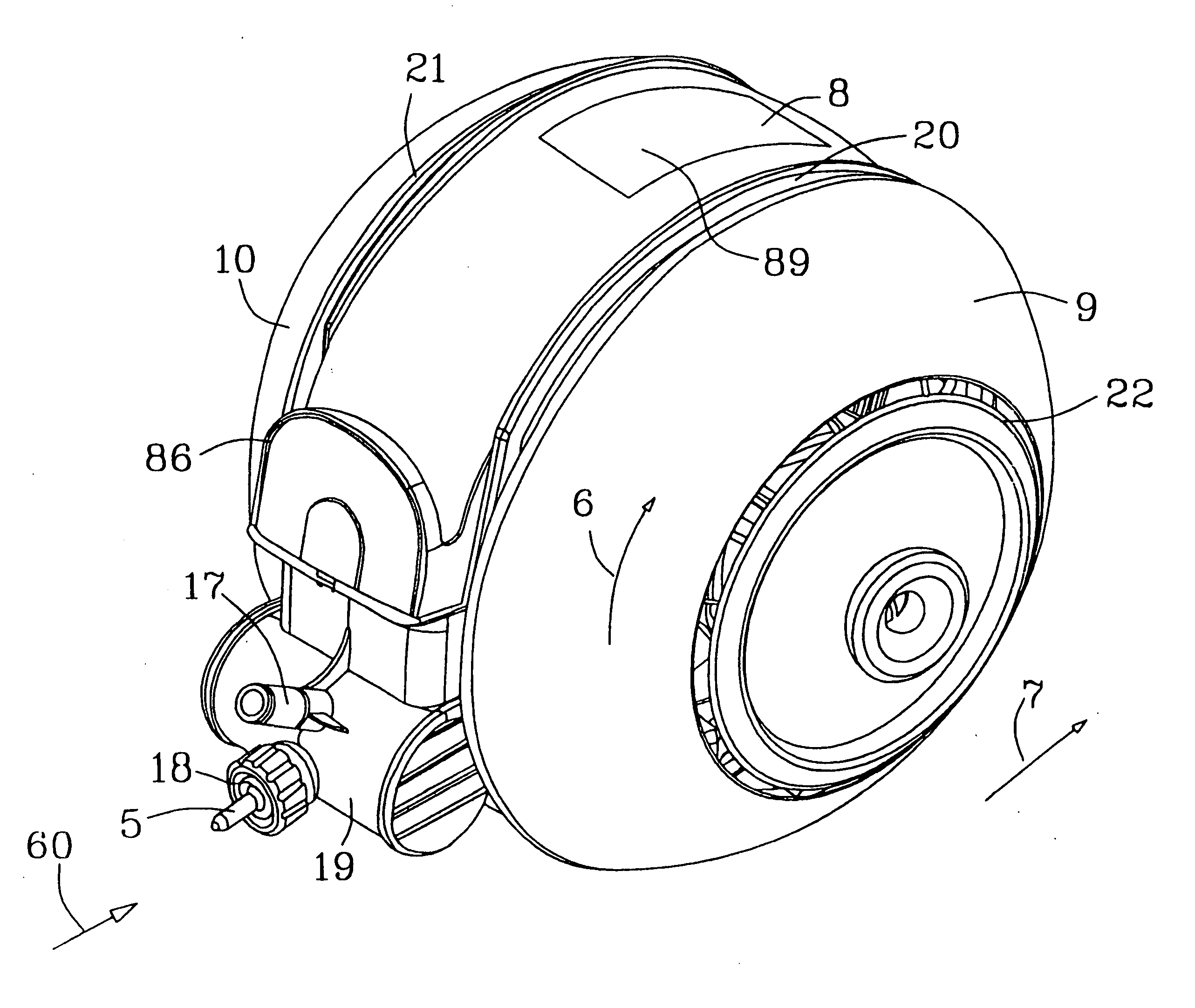
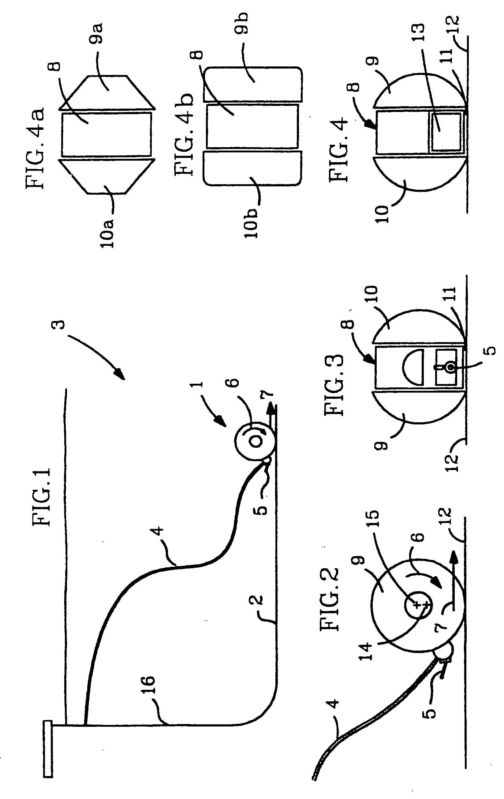
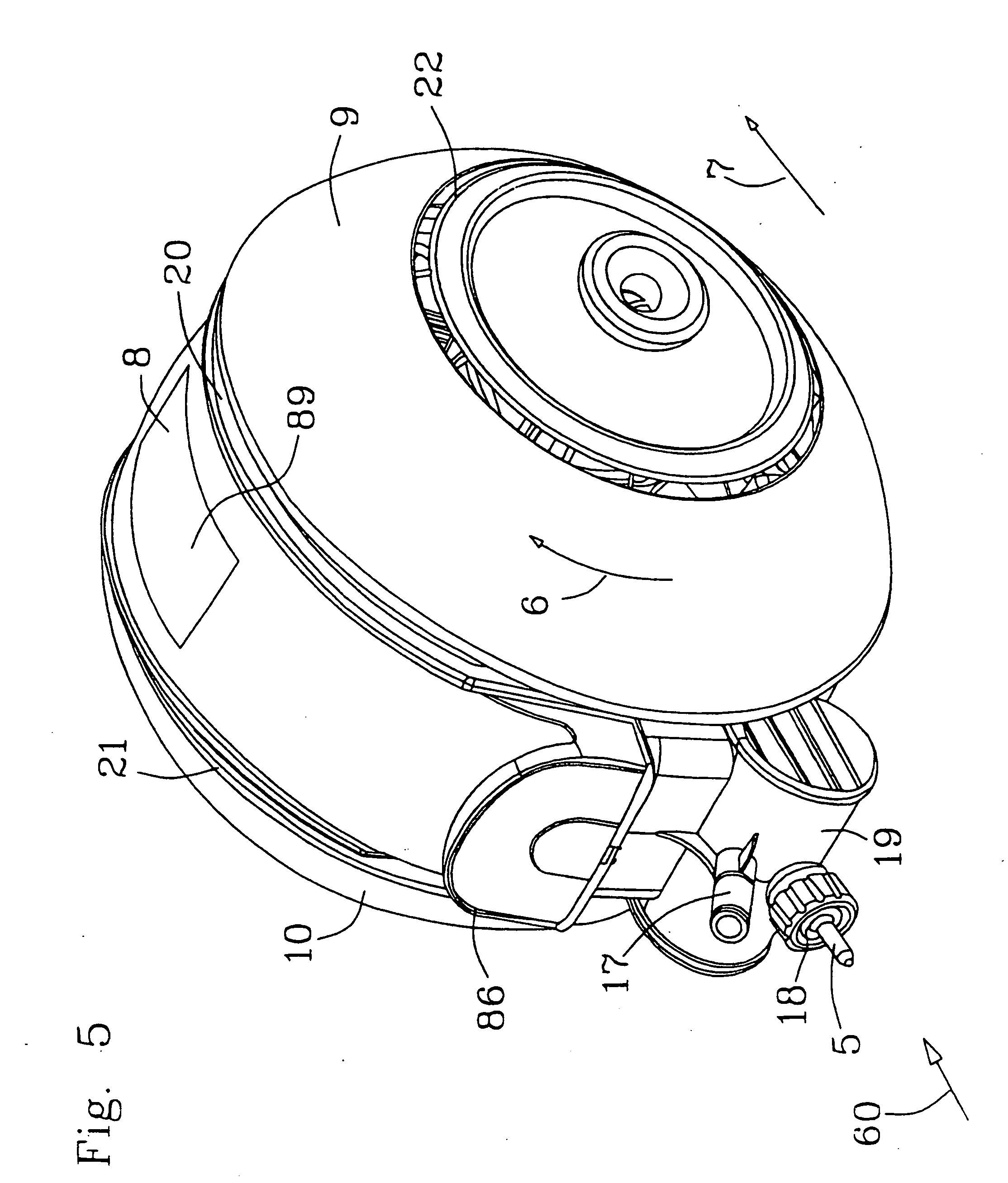
[0060]FIG. 1 schematically shows a push side cleaner 1 located on a bottom surface 2 of a pool 3. The pool cleaner 1 has a hose 4 connected to the push side of a water circulation system which circulates and filters water for the pool. The pool cleaner 1 has a nozzle 5 which jets water rearwardly of the pool cleaner so as to assist in propelling it along the pool surface and the nozzle is mounted in a ball joint so that it can be angled, or it can be manufactured in a fixed angle position, as shown by reference numeral 85 in FIG. 17. The angle of the nozzle may be made suitable also to press the pool cleaner to some extent onto the surface of the pool along which it is moving. The pool cleaner moves by rotation of the outer segments of the cleaner in the direction indicated by the arrow 6 so that the pool cleaner moves along the pool surface in the direction indicated by the arrow 7.

[0061] As shown in FIGS. 2, 3 and 4 the push side pool cleaner is generally spheroidal in shape of i...


PUM


Abstract

A push side pool cleaner (1) has a spheroidal overall shape, within this shape two outer segments (9, 10) serve as wheels and a central zone (88) carries a suction passage (33) and a debris collector (32) also located entirely within the overall shape. The wheels are driven directly by water jets (44, 45) without any gears or other transmission. A flow splitter is provided in the cleaner (1) to divide push side water flow between the jets (44, 45) which drive the wheels and jets (43) which provide impulsion to the suction passage (33).

Description

CROSS-REFERENCE TO RELATED APPLICATIONS [0001] This application is a continuation of and claims priority to (allowed) U.S. patent application Ser. No. 10 / 387,932 filed on Mar. 13, 2003, which is a continuation of and claims priority to U.S. patent application Ser. No. 09 / 673,873 filed on Feb. 28, 2001 (now U.S. Pat. No. 6,601,255), which is the U.S. national phase entry of International Patent Application No. PCT / US99 / 11035 filed on May 19, 1999, which in turn claims priority to South African Patent Document No. 98 / 04346 filed on May 22, 1998, South African Patent Document No. 98 / 09806 filed on Oct. 28, 1998 and South African Patent Document No. 99 / 02896 filed on Apr. 23,1999.FIELD OF THE INVENTION [0002] This invention lies in the field of pool cleaners which are driven by water circulated by a pump. The invention is not necessarily limited to “automatic pool cleaners”, depending on what precisely is understood by this term, but the term “automatic pool cleaners” is often used in t...

Claims


Application Information

Patent Timeline
Patent Type & Authority Applications(United States)
IPC IPC(8): E04H4/16
CPCE04H4/1654
Inventor VAN DER MEYDEN, HENDRIKUS JOHANNESWADMAN, ALEXIS ADRIAN FELIPEMOORE, MICHAEL EDWARD
Owner ZODIAC POOL CARE
Why Eureka
Try Eureka