
Control of functions and sounds using electronic hand glove

Inactive Publication Date: 2006-09-21
K GROUP INDS FAR EAST
View PDF6 Cites 15 Cited by
  • Summary
  • Abstract
  • Description
  • Claims
  • Application Information

AI Technical Summary

Benefits of technology

[0006] The present invention provides different apparatus and systems for remotely controlling functions performed and sounds rendered by electronic devices such as toys using simple hand motions and finger flexing.

Problems solved by technology

In many instances, however, the apparatus for control can be a bulky device that may utilize a bewildering array of knobs, dials, or other mechanisms for effecting control.
With respect to both the performance of functions and evocation of sounds, however, many toy devices do not enable a child's controlling which functions are performed or which sounds are played.
Nor, in many instances, is the child able to control remotely the order in which different various functions are performed or sounds are played by the toy.
That is, the toy is limited to performing pre-selected functions and playing pre-selected sounds in a pre-designated order.
Moreover, conventional toys typically constrain a child's play activity and imagination by requiring the child to instigate actions with or evoke sounds from a toy by manually activating a switch, button, or similar such device.

Method used


Image

  • Control of functions and sounds using electronic hand glove
  • Control of functions and sounds using electronic hand glove
  • Control of functions and sounds using electronic hand glove

Examples


Embodiment Construction

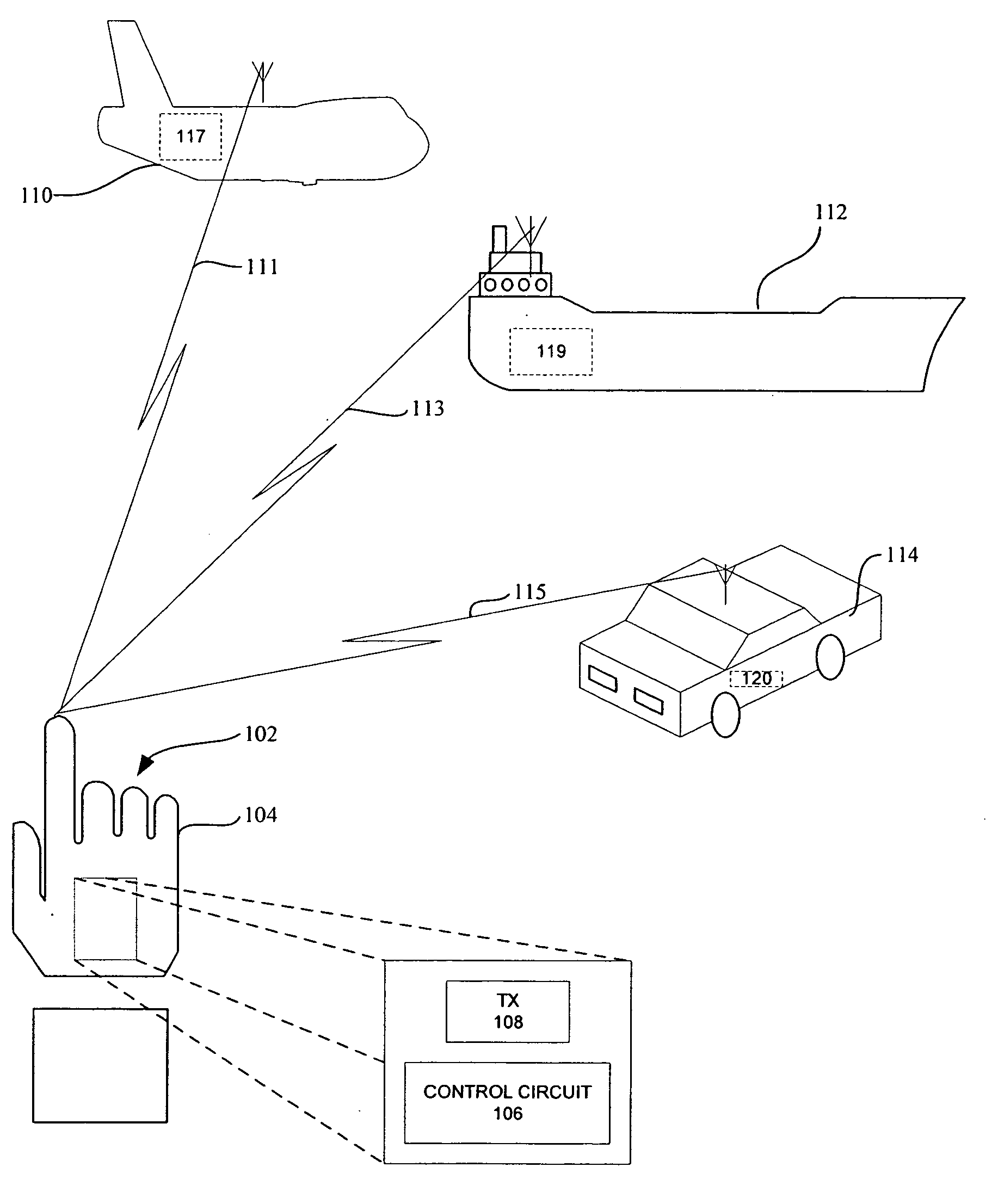
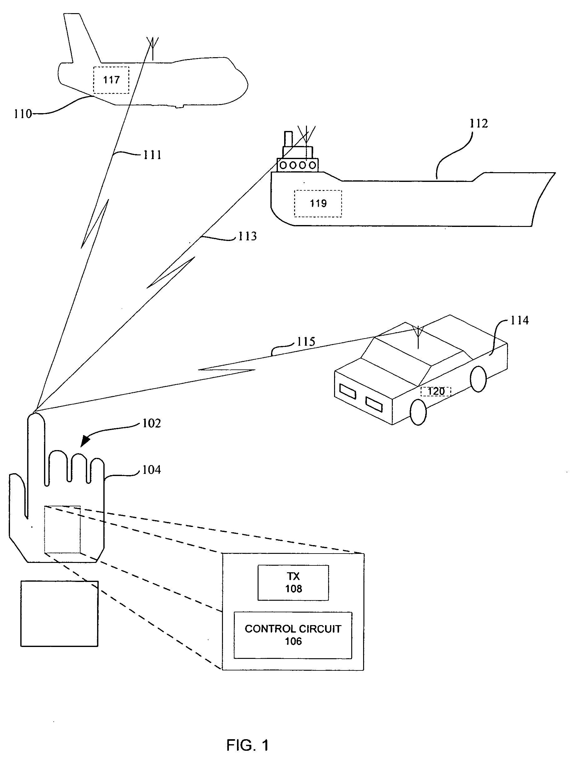
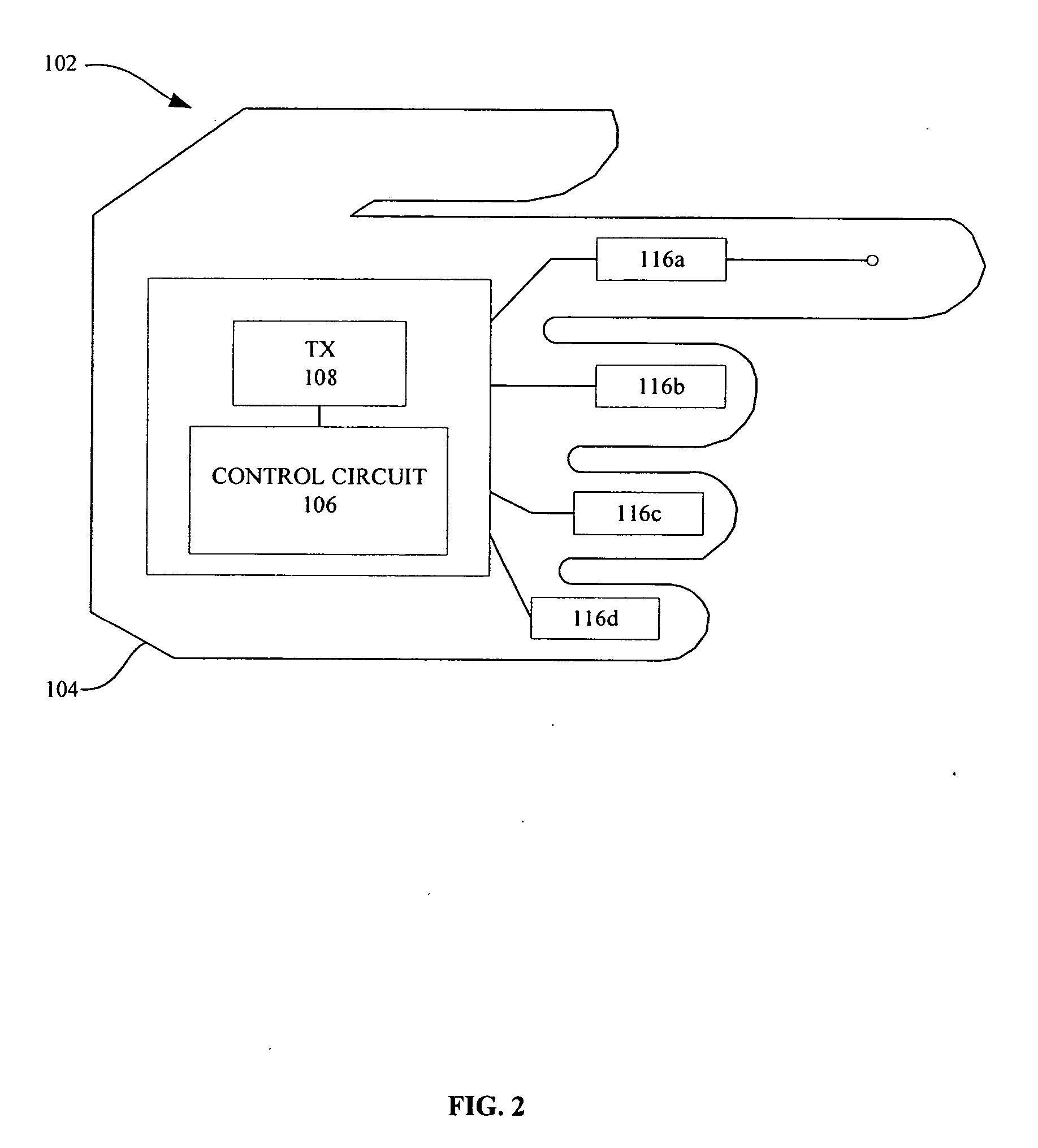
[0018]FIG. 1 is a schematic diagram of a system 100 according to one embodiment of the present invention. The system 100 illustratively includes a glove assembly 102 comprising a material 104 configured to be worn on the hand of an adult or child, and circuitry connected therewith for controlling one or more selectively operable devices. More particularly, the circuitry of the glove assembly 102 illustratively comprises a control circuit 106 enmeshed in the material 104 or otherwise mounted to the glove assembly 102. As illustrated, the circuitry of the glove assembly 102 further includes a signal transmitter 108 communicatively connected with the control circuit 106, the signal transmitter 108 also being enmeshed in the material or otherwise mounted to the glove assembly. Illustratively, the selectively operable devices of the system 100 include a toy airplane 110, a toy ship 112, and a toy automobile 114, each of which undertakes movements and / or performs functions as dictated by ...


PUM


Abstract

An apparatus for remotely controlling a selectively operable device is provided. The apparatus includes a glove assembly (102) comprising a material (104) worn on a hand. The apparatus also includes sensors (116a-d) mounted to the glove assembly (102), each of the sensors generating at least one response signal in response to a movement of the hand or a flexing of a finger of the hand. The apparatus also includes a control circuit (106) mounted to the glove assembly (102) and communicatively connected to the sensors (116a-d) for generating at least one control instruction in response to the response signals. The apparatus further includes a signal transmitter (108) mounted to the glove assembly (102) and communicatively connected to the control circuit (106) for transmitting a wireless signal containing the at least one control instruction, the at least one control signal causing the device to perform at least one predefined electromechanical function.

Description

BACKGROUND [0001] 1. Field of the Invention [0002] The present invention is related to the field of electronic devices, and, more particularly, to the control of electronic devices. [0003] 2. Description of the Related Art [0004] Electronic devices are a ubiquitous feature of modern life, various such devices performing an ever-increasing number of different functions. Electronic toys, for example, can be remotely controlled to perform a variety of different play-related functions. A gas-powered, propeller-driven toy airplane, for example, can be made to fly according to a remotely controlled pattern using wirelessly transmitted electronic instructions. Similarly, a propeller-driven toy ship can be steered using a remotely controlled rudder. In many instances, however, the apparatus for control can be a bulky device that may utilize a bewildering array of knobs, dials, or other mechanisms for effecting control. Moreover, the various control apparatus may vary widely in operation and...

Claims


Application Information

Patent Timeline
IPC IPC(8): G10H1/00
CPCA63H30/04G10H7/00G10H2220/311G10H2220/326G10H2220/395G10H2220/461G10H2240/211
Inventor KAVANA, JORDAN STEVEN
Owner K GROUP INDS FAR EAST
Learn More