
Rolling heel, forward facing rowing system

Inactive Publication Date: 2005-09-06
VECTOR MAGNETICS
View PDF18 Cites 21 Cited by
  • Summary
  • Abstract
  • Description
  • Claims
  • Application Information

AI Technical Summary

Benefits of technology

[0007]The handle includes a rod portion that is pivotally engaged at one end to the oar and is secured at its opposite end to the flexible cable. A grip is secured to the rod at an angle of about 60° to allow a rower to grasp the handle to manipulate the oar in forward (recover) and rearward (power) strokes. The pivotal connection of the handle also allows the rower to pivot the handle in one direction to rotate the oar to feather it for the return stroke and to pivot the handle in the opposite direction to rotate the oar to square it for the power stroke by simple wrist motions in synchronism with the foreward and rearward motion of the oar.

Problems solved by technology

Every backward facing rower has experienced serious safety concerns after encountering unexpected obstacles, even when mirror arrangements are used to look ahead.
One such system provides footrests that slide in a track and are connected by ropes to oars in a normal, backwards facing rowboat, but this system does not require fastening of the feet to a foot support, does not have free foot movement, and more importantly does not have favorable foot ergonomics.
In other systems, the entire oar rigging, including its full weight, must also be moved forward and backward with each stroke, thus increasing the required force and effort of the user.
The swinging arm motion has poor ergonomics, however, because of the unnatural relationship in the positioning and relative motion between the legs with the rest of the body.
Such systems suffer from undue mechanical complications, with much inherent friction, and probable unreliability in a wet environment.

Method used


Image

  • Rolling heel, forward facing rowing system
  • Rolling heel, forward facing rowing system
  • Rolling heel, forward facing rowing system

Examples


Embodiment Construction

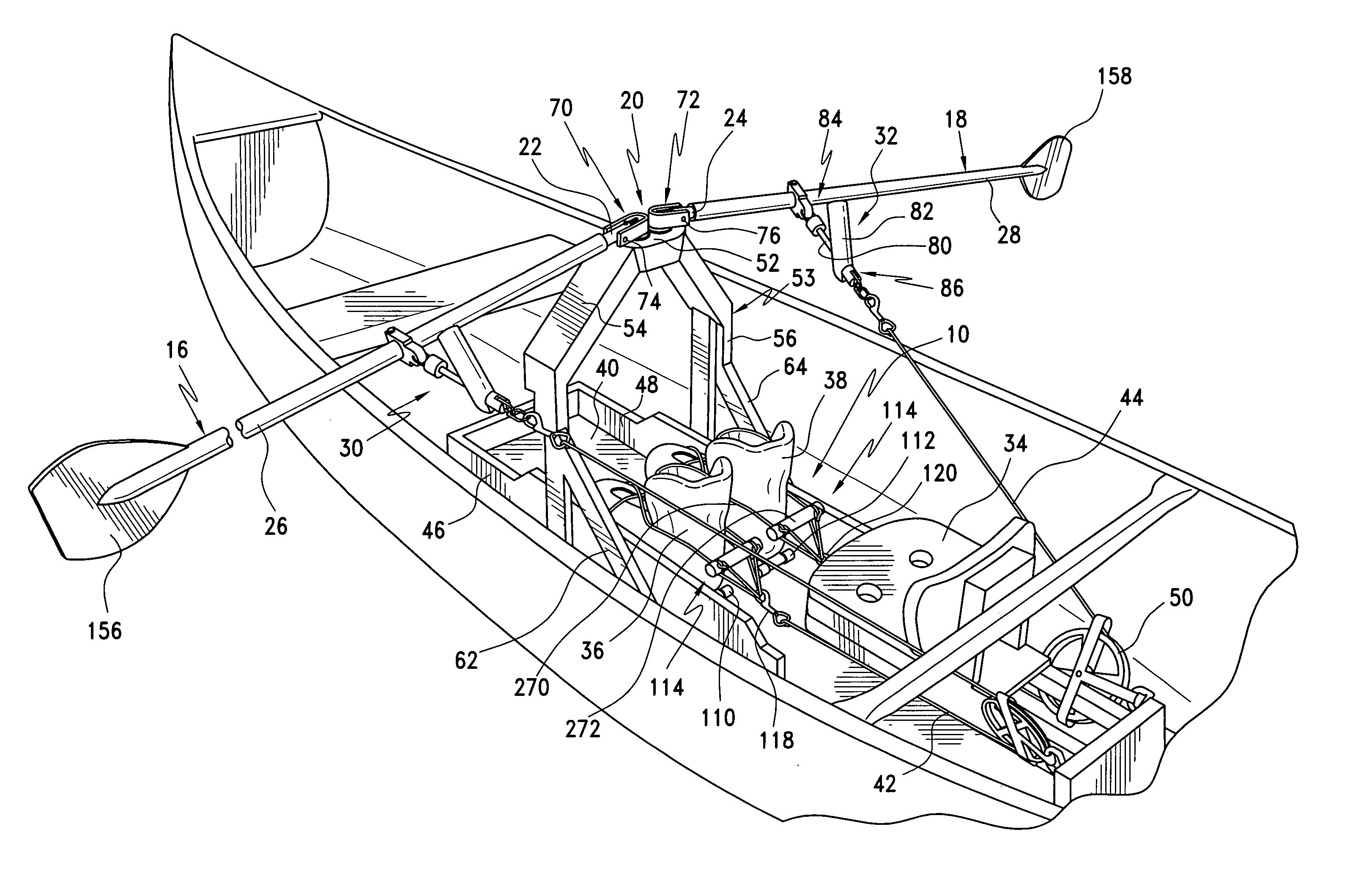
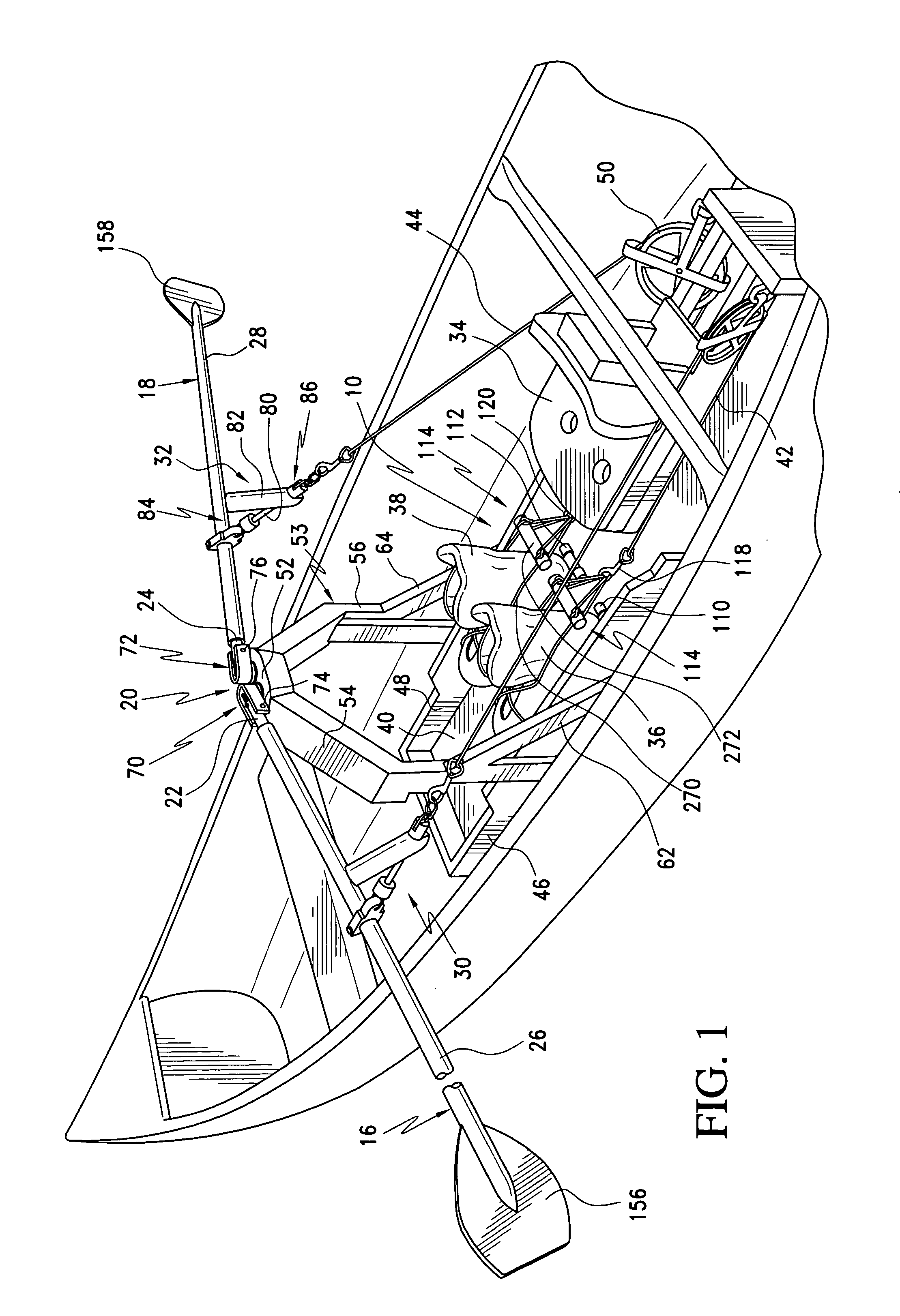
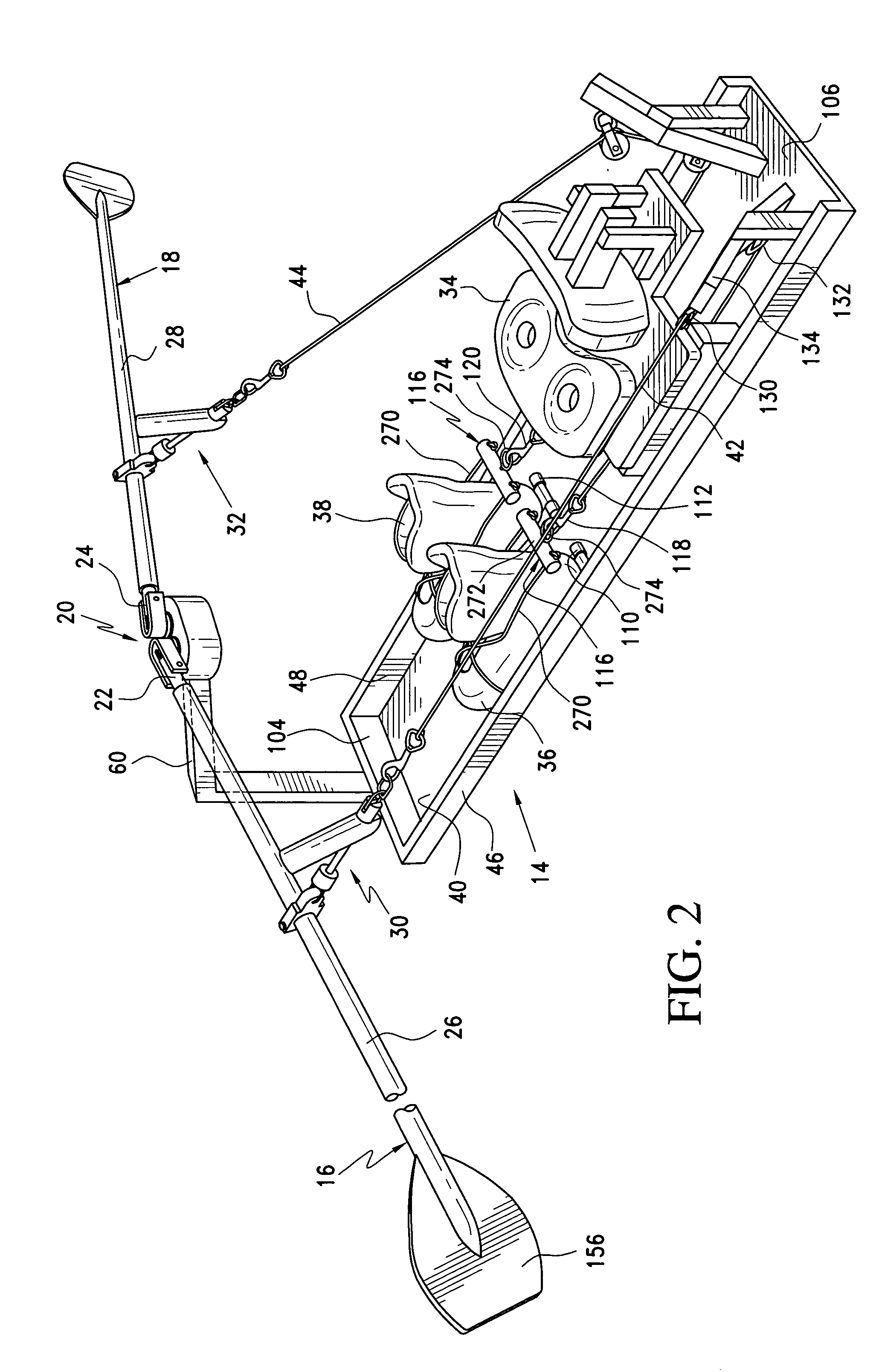
[0028]Turning now to a more detailed description of the invention, FIG. 1 illustrates a first embodiment of a front-rowing system in the form of a unitary “drop in” rowing apparatus 10 mounted in a suitable boat hull 12. Although the boat hull is illustrated as a canoe, it will be understood that it may take any desired form, and that a canoe is illustrated for purposes of convenience. It will also be understood that for purposes of the following description, the system is illustrated as a unitary assembly capable of being mounted in any suitable boat hull, but that it is often preferable to incorporate the system of the invention as an integral part of the boat design. A second embodiment of the invention is illustrated in FIG. 2 at 14, wherein the forward-facing rowing apparatus incorporates a modified oar support apparatus, to be described in greater detail below. In both embodiments, similar features are identified by the same reference numerals.

[0029]The self-contained, or unit...


PUM


Abstract

A new and improved leg assisted forward facing rowing system is disclosed wherein a rower applies leg power to propel a boat by means of a rope connected between his or her foot and an oar. A unique feature is a roller, fastened under the heel of the rower's foot, that rolls along the bottom of the boat supporting the weight of the rower's leg while the reciprocating motion of the leg is transmitted by rope going through pulleys to reverse the force applied to the oar. The oar is pivoted at the center of the boat above the rower's knees by a mechanism that includes provision for applying lifting force to support the oar weight thereby holding the oar blade out of the water when no force is applied. The rower's legs, back and arms simultaneously apply rowing force. Feathering at the end of a stroke and squaring action at the beginning are provided by wrist action to rotate the oar blade. Ergonomically good features of a conventional sliding seat racing scull rowing are thereby incorporated into a forward facing rowing apparatus.

Description

[0001]This application claims the benefit of U.S. Provisional Application No. 60 / 570,824, filed May 14, 2004, the disclosure of which is hereby incorporated herein by reference.BACKGROUND OF THE INVENTION[0002]The ergonomics of conventional scull and shell rowing, where a rower's arms, legs and back apply propelling force to the oars, are very good. The rower grasps the oars with his hands while sitting on a sliding seat facing the rear of the boat with his feet fastened in boots on the bottom of the boat. At the start of the power part of the stroke, the seat is located toward the rearward end of its motion with the rowers legs flexed, the rower lifts the oar handle to place the blade of the oar in the water, and the legs, then the back and finally the arms supply force to the oar as the rowers legs extend to slide the seat toward the forward end of its motion, propelling the boat forward. At the end of the stroke the rower uses wrist action to rotate the oar, thereby “feathering” ...

Claims


Application Information

Patent Timeline
IPC IPC(8): B63H16/00B63H16/06B63H16/10
CPCB63H16/107
Inventor KUCKES, ARTHUR F.
Owner VECTOR MAGNETICS
Learn More