
Pan lifting implement

a technology of lifting implements and pans, which is applied in the field of tools with jaws, can solve the problems of affecting the use of kitchen equipment, affecting the use of kitchen appliances, and affecting the use of kitchen appliances, and achieves the effect of reducing the likelihood of scalds, burns, and other lost time injuries

Inactive Publication Date: 2006-09-21
ROMSBURG ROY +2
View PDF14 Cites 9 Cited by
  • Summary
  • Abstract
  • Description
  • Claims
  • Application Information

AI Technical Summary

Benefits of technology

[0004] In light of the problems associated with the known practices associated with moving serving pans to and from steam tables, it is a principal object of the invention to provide an implement that permits a user to safely lift a serving pan from a hot well, steamer or food warmer and to transport the pan to any desired location. Use of the implement minimizes the likelihood of scalds, burns, pinched fingers and other lost time injuries.
[0005] Still another object of the invention is to provide an implement of the type described that firmly grips a pan as it is being lifted and carried so that the likelihood of embarrassing and costly food spills is minimized. Further, the implement impresses onlookers who see pans being lifted and carried in an expert manner.
[0006] It is another object of the invention to provide an implement of the type described that does not, in ordinary use, contact food in a serving pan, thereby minimizing the likelihood of food contamination. Thus, use of the implement promotes good sanitation practices.
[0007] It is an object of the invention to provide improved elements and arrangements thereof in a pan lifting implement for the purposes described that is lightweight in construction, inexpensive to manufacture, and dependable in use.

Problems solved by technology

These pans are typically hot, heavy and bulky, necessitating that they be handled with great care to avoid scalding.
Furthermore, a lack of handles makes serving pans difficult to grasp, let alone lift and carry.
Of course, a spill from a pan used at a steam table wastes food and can be time-consuming to clean.
Regardless of the direction of movement of the pan, however, the towel sometimes falls into it, contaminating food and making it unfit for human consumption.

Method used


Image

  • Pan lifting implement
  • Pan lifting implement
  • Pan lifting implement

Examples


Embodiment Construction

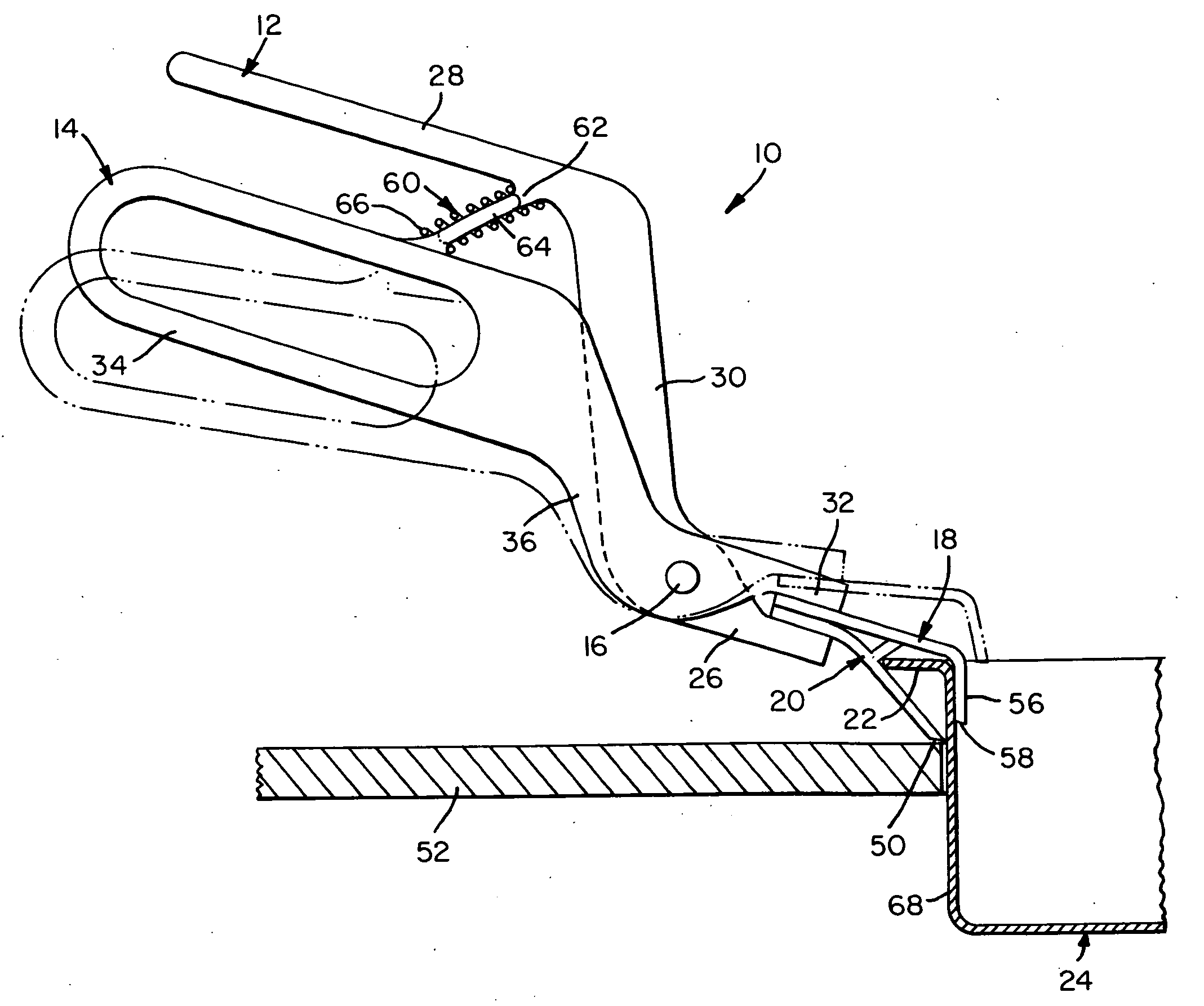
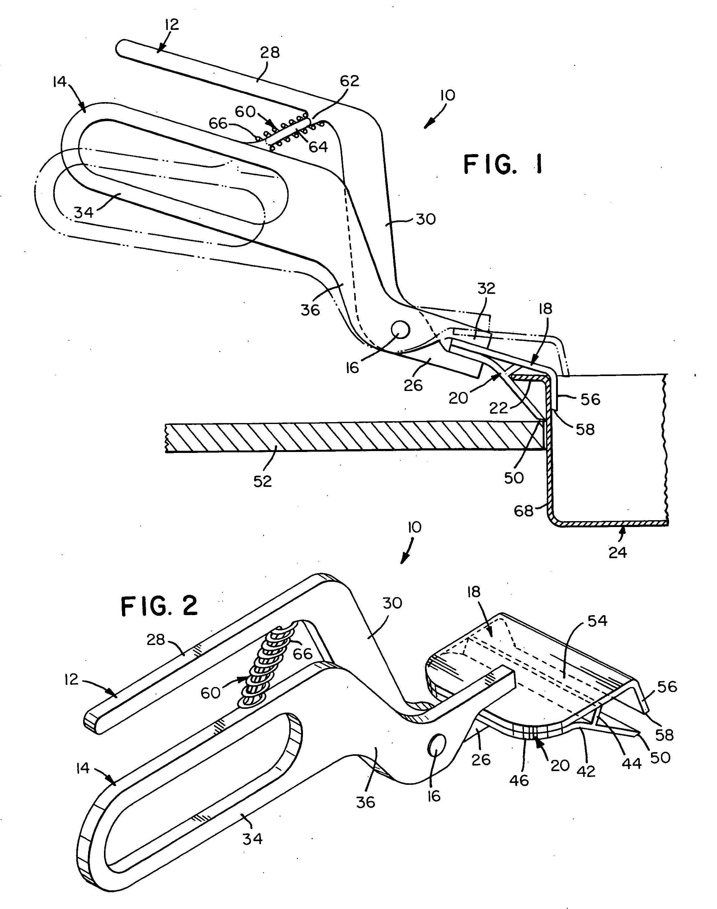
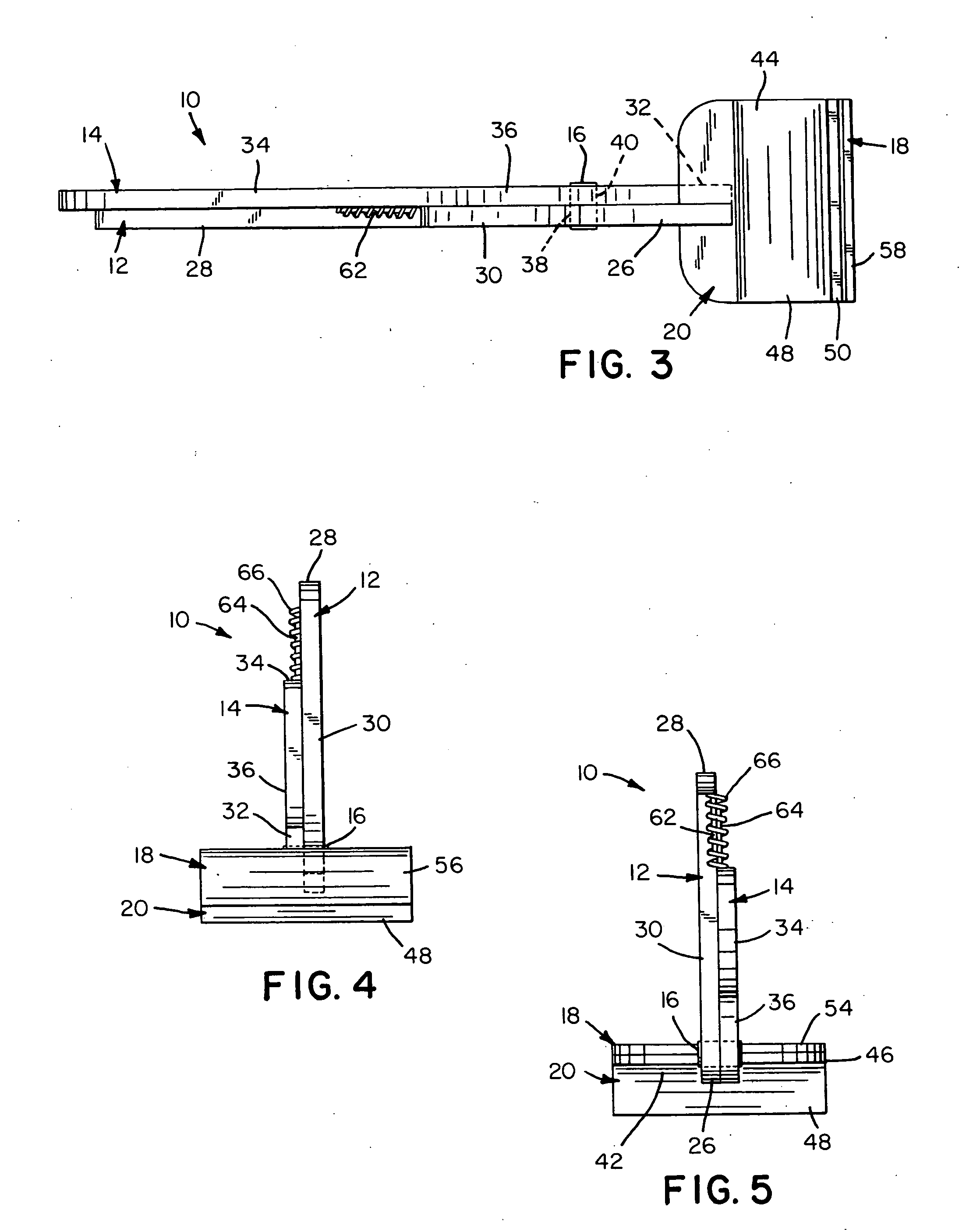
[0017] Referring now to the FIGS., a pan lifting implement in accordance with the present invention is shown at 10. Implement 10 includes a pair of levers 12 and 14 connected together by a pivot pin 16 in the crisscrossing manner of pliers. Levers 12 and 14 carry a pair of jaws 18 and 20 for grasping the peripheral rim 22 of a pan 24.

[0018] Lever 12 has a keeper portion 26 at its front end and a handle portion 28 at its rear end joined together by a crosspiece 30. Keeper portion 26 and handle portion 28 are bars that are vertically offset so that keeper portion 26 has a lower elevation than that of handle portion 28 during normal usage of implement 10. Crosspiece 30 joins keeper portion 26 and handle portion 28 at obtuse angles to maintain the offset relationship between keeper portion 26 and handle portion 28.

[0019] Lever 14 has a keeper portion 32 at its front end and a handle portion 34 at its rear end joined together by a crosspiece 36. Keeper portion 32 is a bar having a leng...


PUM


Abstract

An implement for lifting pans from steam tables. The implement includes a pair of pivotally connected, crisscrossing levers. A pair of jaws, each is affixed to the front end of a respective one of the levers and extends laterally beyond the opposite sides of a respective one of the levers. One of the jaws has a lifting plate from the middle of which a backstop extends upwardly and forwardly at an acute angle to form a concavity into which the outer edge of a rim of a pan can be inserted. The other one of the jaws has a shank portion that is positioned above the backstop and a hook portion that extends downwardly from the shank portion for grasping the inner edge of a rim of a pan.

Description

FIELD OF THE INVENTION [0001] The present invention relates generally to tools with jaws positioned by relatively movable plural handles and, more particularly, to such tools with jaws that extend laterally beyond the side edge planes of the handles. BACKGROUND OF THE INVENTION [0002] For decades, caterers and restaurateurs have confronted the problems associated with moving food-filled, serving pans to and from steam tables. These pans are typically hot, heavy and bulky, necessitating that they be handled with great care to avoid scalding. Furthermore, a lack of handles makes serving pans difficult to grasp, let alone lift and carry. Of course, a spill from a pan used at a steam table wastes food and can be time-consuming to clean. [0003] An improvised method is normally used to dislodge a pan from a steam table. It may involve using a knife or fork as a prying tool to raise the lip of a pan from a steam table and, then, grasping the pan with towel-covered hands. Once grasped, the ...

Claims


Application Information

Patent Timeline
Patent Type & Authority Applications(United States)
IPC IPC(8): A47J45/07
CPCA47J45/10
Inventor ROMSBURG, ROYROMSBURG, PAUL JR.ROMSBURG, PAUL SR.
Owner ROMSBURG ROY
Learn More