Redundant power system with no latent single failure point

a power system and latent single technology, applied in emergency power supply arrangements, instruments, transportation and packaging, etc., can solve the problems of not operating correctly without electrical power, high cost of providing fully-redundant power supplies in this manner, and one may be more expensive to use than another

Active Publication Date: 2006-09-21
NETWORK APPLIANCE INC
View PDF11 Cites 20 Cited by
  • Summary
  • Abstract
  • Description
  • Claims
  • Application Information

AI Technical Summary

Problems solved by technology

All such machines share the common characteristic that they will not operate correctly without electrical power.
Unfortunately, providing fully-redundant power supplies in this manner is expensive: two supplies cost twice as much as one.
Furthermore, although the incoming power circuits may b

Method used


Image

  • Redundant power system with no latent single failure point
  • Redundant power system with no latent single failure point
  • Redundant power system with no latent single failure point

Examples


Embodiment Construction

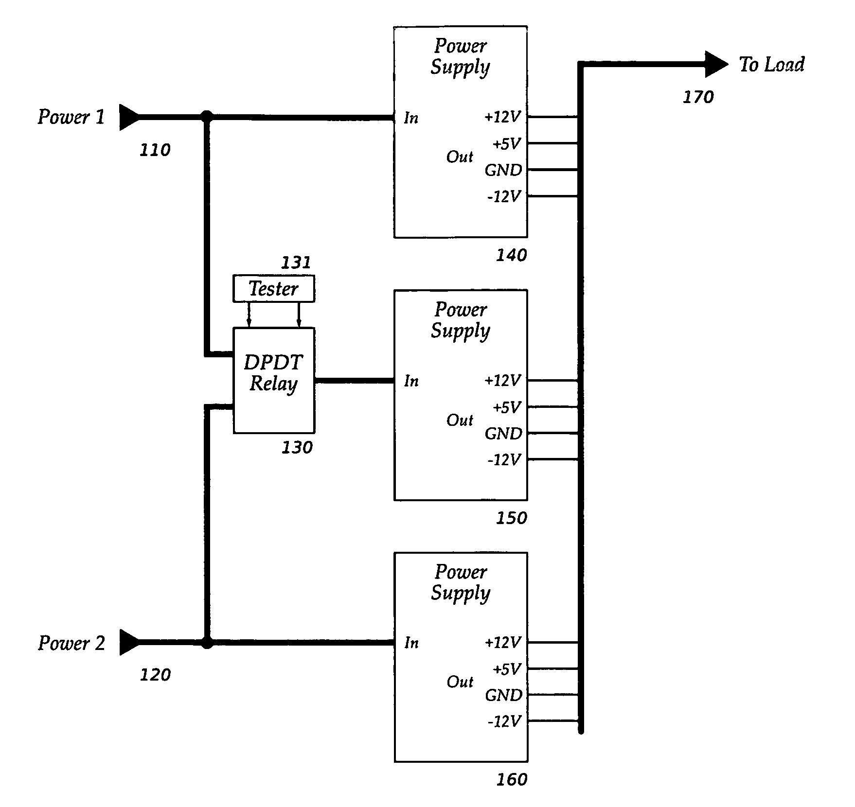
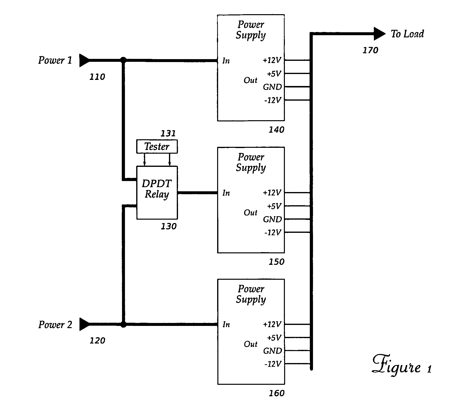
[0015] Embodiments of the invention use three or more power supplies to provide reliable power to a load such as a general- or special-purpose computer system. Each power supply may be rated at less than the total power required by the load. At least one of the power supplies can obtain its incoming electrical power from one of at least two sources, through a switching network. The switching network can be tested using a technique such as described in co-pending application [INSERT APPLICATION NUMBER] to eliminate a latent single-point failure source.

[0016] A simple embodiment of the invention is shown in FIG. 1. There, a plurality of power supplies 140, 150 and 160 receive electrical power in one form from one of power connections 110 or 120, and provide electrical power in another form to a load 170. Power connections 110 and 120 may provide power at any frequency (including DC input) and voltage that is within the input specifications of power supplies 140, 150 and 160, and the ...


PUM


Abstract

A redundant power supply system with several individual power supplies, each connected to one of several power inlets. At least one power supply can be connected to a selectable one of the several power inlets by means of a steering network.

Description

BACKGROUND [0001] Electrically-operated machines perform a wide range of functions, from the whimsical to the life-saving. All such machines share the common characteristic that they will not operate correctly without electrical power. Accordingly, as the purpose a machine serves becomes more important, so too are the measures taken to ensure that the machine's power source will not be interrupted. [0002] General- and special-purpose computing devices commonly require direct current (DC) power at several voltages. These voltages are produced by a system component called a power supply, which typically converts electrical energy from the alternating current (AC), high voltage form in which it is often delivered, to the lower DC voltages used by the device. Power supplies are rated in terms of the maximum power they can supply at their output voltages. The cost of a power supply is roughly proportional to its rated power: a 100 watt (W) supply may cost approximately half as much as a ...

Claims


Application Information

Patent Timeline
IPC IPC(8): H02J9/00
CPCG06F1/30G06F11/2015H02J1/102H02J1/001
Inventor ZANSKY, ZOLTANJACOBSEN, WILLIAM F. M.SHAH, SANDEEP K.
Owner NETWORK APPLIANCE INC
Why Eureka
Try Eureka