
Fault isolation and provisioning for optical switches

a technology of optical switches and fault isolation, applied in the field of optical communication, can solve the problems of inability to store network-wide provisioning data, inability to be generally available at the operator's terminal, and inability to identify faults with high precision, so as to save the operator time and money

Inactive Publication Date: 2007-10-11
RPX CORP
View PDF72 Cites 22 Cited by
  • Summary
  • Abstract
  • Description
  • Claims
  • Application Information

AI Technical Summary

Benefits of technology

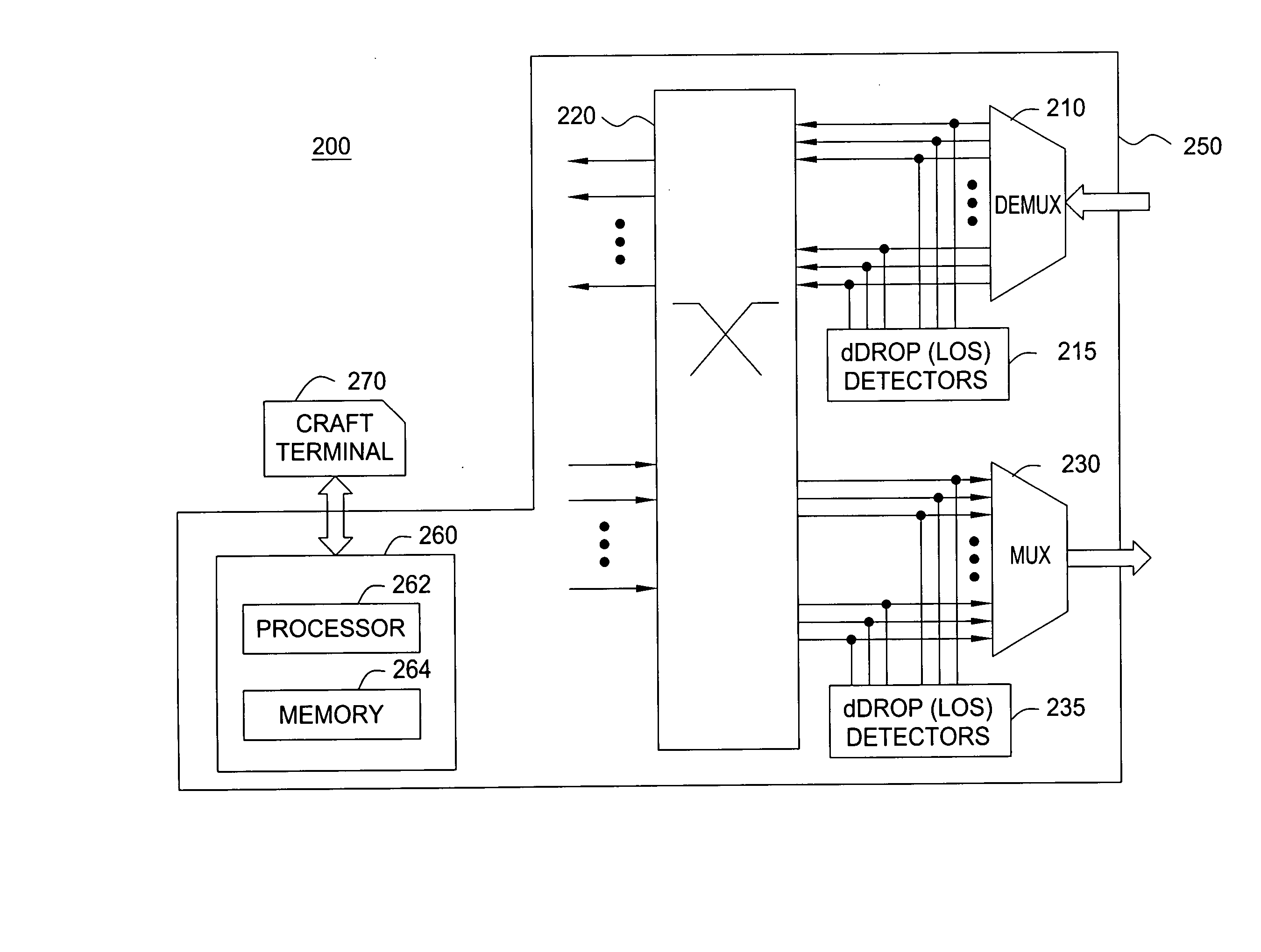
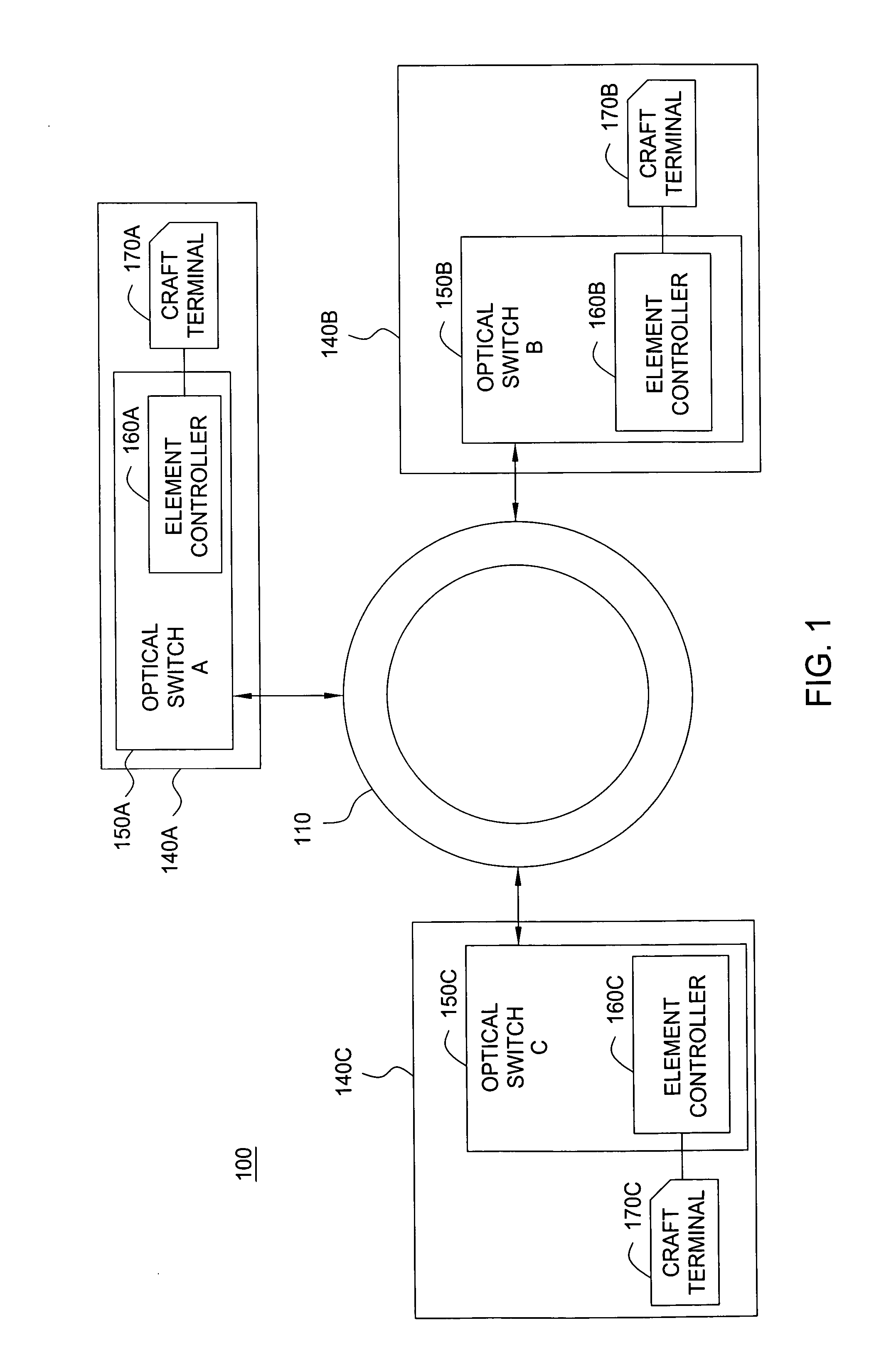
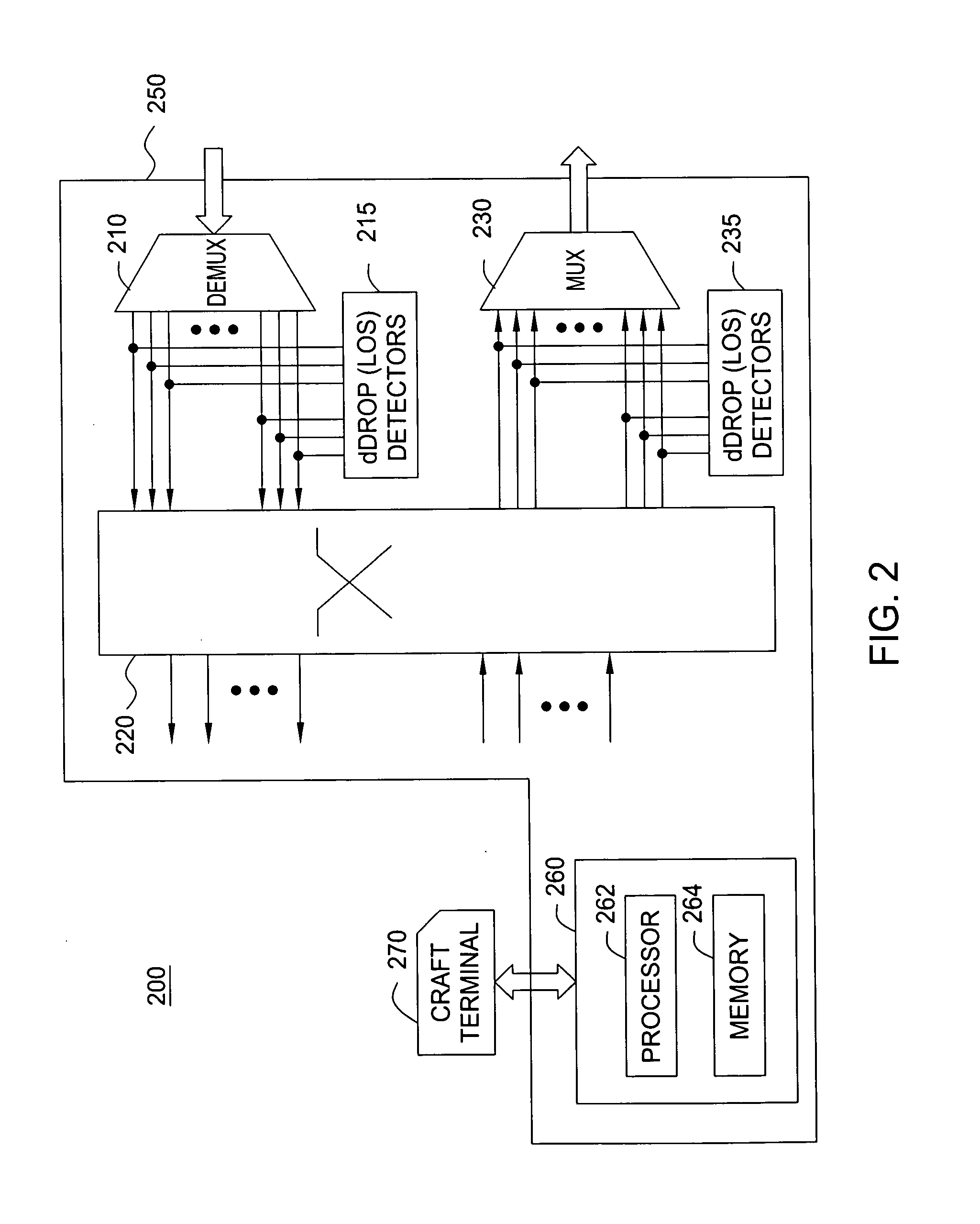
[0004] In accordance with one embodiment of the invention, each optical switch includes an element controller. The provisioning information is stored within the optical switches and is retrieved by every element controller. The optical switches perform failure isolation according to their provisioning data. The optical switches monitor each channel for loss of signal (LOS). The provisioning data is shared autonomously between the optical switches, allowing the switches to retrieve the provisioning information of the network topology from any other optical switch in the network. Fault isolation is effected on the level of optical switch provisioning following the paradigm of “single alarm for single fault,” thus avoiding alarm floods and ambiguous alarms, saving the operator time and money.

Problems solved by technology

Network-wide provisioning data is not stored within the optical switches and, therefore, not generally available at the operator's terminal (i.e., craft terminal).
Because the optical switches do not have an unlimited number of alarm detectors, such means of isolating and identifying fault is very imprecise.

Method used


Image

  • Fault isolation and provisioning for optical switches
  • Fault isolation and provisioning for optical switches
  • Fault isolation and provisioning for optical switches

Examples


Embodiment Construction

[0012] The present invention is generally described within the context of fiber-optic communication systems. It will be appreciated by those skilled in the art that the invention may be utilized within the context of an optical add / drop multiplexer (OADM) within an optical switch in an optical network. Other provisionable elements within the communication systems also benefit from the invention.

[0013]FIG. 1 depicts a high-level block diagram of a fiber-optic communication system suitable for use with the present invention. In one embodiment, the communication system 100 includes a communication network 110 having a plurality of optical nodes 140A, 140B and 140C.

[0014] The network 110 transports information between optical nodes. In one embodiment, the network 110 is a ring network structure. In another embodiment, the network 110 topology comprises non-ring networks (not shown) such as a mesh, star or other types of network structures. In a further embodiment, the network includes...


PUM


Abstract

The present invention includes method and apparatus for storing provisioned information within the optical switches and retrievable by every controller. The optical switches perform failure isolation according to their provisioning information. The optical switches monitor each channel for loss of signal. The provisioning information is shared autonomously between the optical switches allowing the switches to retrieve the provisioning information of the network topology from any other optical switch in the network. Fault isolation is done by the optical switch on the level of optical switch provisioning following the paradigm of “single alarm for single fault,” thus avoiding alarm floods and ambiguous alarms, thereby saving the operator time and money.

Description

FIELD OF THE INVENTION [0001] The invention is related to the field of optical communications, and in particular, for fault isolation and provisioning for optical switches. BACKGROUND OF THE INVENTION [0002] In a conventional fiber-optic communication system, optical switches store their own local switching data. Network-wide provisioning data is not stored within the optical switches and, therefore, not generally available at the operator's terminal (i.e., craft terminal). When there is a fault in the network, a network management system tries to identify the root cause of the fault using alarm information received from the optical switches (and other elements in the network). Because the optical switches do not have an unlimited number of alarm detectors, such means of isolating and identifying fault is very imprecise. SUMMARY [0003] Various deficiencies of the prior art are addressed by the present invention for enhanced per wavelength fault isolation and provisioning of optical ...

Claims


Application Information

Patent Timeline
IPC IPC(8): H04B10/08
CPCH04B10/0791H04B10/07955H04Q11/0062H04Q2011/0083H04Q2011/0039H04Q2011/0079H04Q2011/0081H04Q2011/0024
Inventor MEYER, GERHARDTHOMAS, WOLFGANG
Owner RPX CORP
Learn More