Fault injection method

A fault injection and fault technology, which is applied in the direction of instruments, simulators, control/regulation systems, etc., can solve problems such as fault injection, system intrusion under test, and low time accuracy, and achieve improved reliability, rapid changes, and broad market prospects Effect

Active Publication Date: 2015-04-22
AVIC NO 631 RES INST
View PDF6 Cites 24 Cited by
  • Summary
  • Abstract
  • Description
  • Claims
  • Application Information

AI Technical Summary

Problems solved by technology

Due to its own reasons, it has some shortcomings, such as only injecting faults into the places wh

Method used


Image

  • Fault injection method
  • Fault injection method
  • Fault injection method

Examples


Embodiment Construction

[0028] The content and effects of the present invention will be described in detail below in conjunction with the accompanying drawings.

[0029] The design method step of the present invention is as follows:

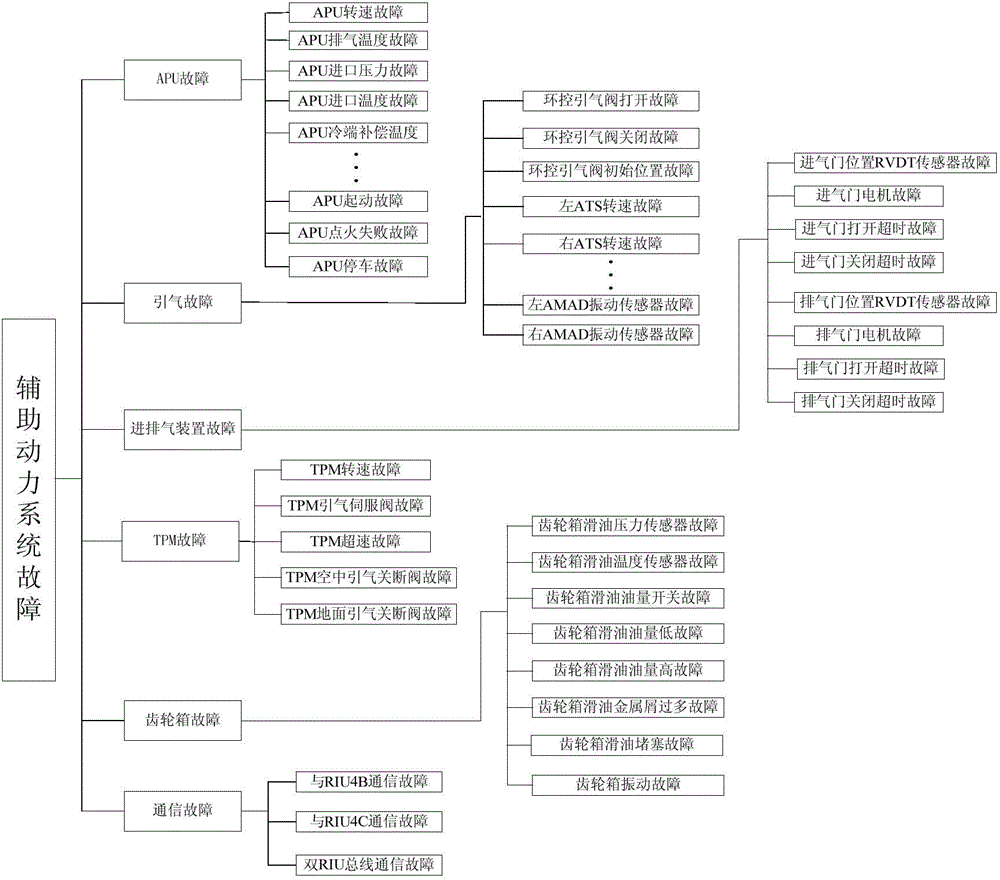
[0030] Step 1, establishment of fault tree. The auxiliary power system has six types of faults, including APU fault, bleed air fault, intake and exhaust device fault, TPM fault, gearbox fault, and communication fault. The established fault tree of the auxiliary power system is as follows: figure 2 shown.

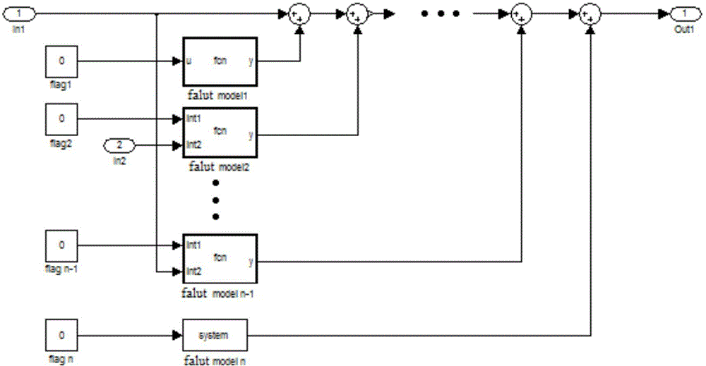
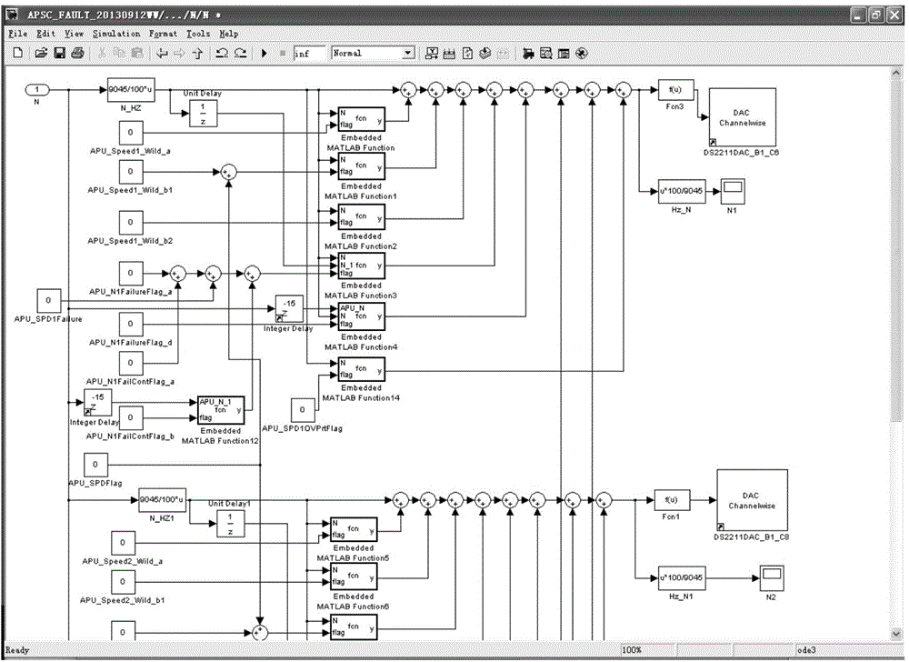
[0031] Step 2, establishment of fault simulation model. Each fault branch on the fault tree has a variety of triggering conditions. According to the triggering conditions of each fault, the Simulink model of the fault is established. In order to quickly and conveniently realize the simulation of multiple fault injection, the fault is added to the normal signal flow input. The trigger point of the model, such as image 3 , 4 Partial Simulink model of APU tach fau...


PUM


Abstract

The invention provides a novel fault injection method. According to the method, a platform for fault injection of an auxiliary power system is designed based on dSPACE, injection of a single fault and a plurality of faults can be configured freely, configuration management and parameter adjustment can be carried out fast through Simulink modeling and a Control Desk, a semi-physical simulation system is formed by an auxiliary power system multi-fault injection model and a physical electronic controller, the probability of generating multiple faults under a ground test and onboard environment is simulated through multi-fault injection, the defects of hardware and software in the system can be found fast in the earlier development process, then effective measures are taken, and the reliability of the system is improved.

Description

technical field [0001] The invention relates to a fault injection method, which is applicable to the simulation test of the auxiliary power system, simulates most of the faults encountered in the engine test process, and discovers the deficiencies of hardware and software in the system during the early development process. Background technique [0002] Fault injection, as a test method to check the fault tolerance of the system, has been widely used in the testing field. The fault injection point is located at the interface between the application and the environment. By simulating various faults that may occur in the real environment at the fault injection point, and observing the reaction of the tested object, its tolerance to faults can be tested. Artificially generating faults and introducing them into the system accelerates the process of system faults and failures. Using the monitoring and analysis of system response information after faults are injected, the goal of t...

Claims


Application Information

Patent Timeline
IPC IPC(8): G05B17/02
Inventor 王伟白洁吕伟刘鑫赵振宇
Owner AVIC NO 631 RES INST
Why Eureka
Try Eureka