
Communication device and communication method

a communication device and communication method technology, applied in the field of spreading spectrum communication system, can solve problems such as modulators or demodulators, and achieve the effect of simplifying hardwar

Inactive Publication Date: 2006-09-21
NAT INST OF INFORMATION & COMM TECH
View PDF9 Cites 49 Cited by
  • Summary
  • Abstract
  • Description
  • Claims
  • Application Information

AI Technical Summary

Benefits of technology

The invention allows for the transmission of data using two different codes that cross each other. These codes are used to spread the data before transmission. On the receiving end, the data is then demodulated by using the same codes that were used to spread it. This eliminates the need for a separate modulator and simplifies the hardware required for the transmission.

Problems solved by technology

The patent text discusses a problem with current communication systems that use a spread spectrum and a pseudo-noise sequence as a spreading code. These systems require a modulator or demodulator for orthogonal modulation and demodulation, which leads to increased hardware requirements. The technical problem is to provide a communication apparatus and method that can effectively use the communication channel without requiring additional hardware.

Method used


Image

  • Communication device and communication method
  • Communication device and communication method
  • Communication device and communication method

Examples


Embodiment Construction

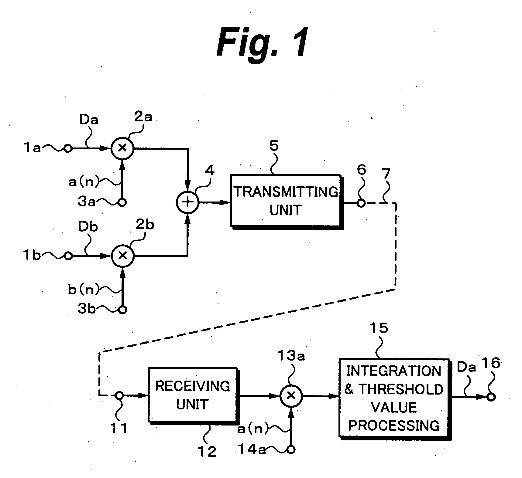
[0023] An embodiment of the invention will be described hereinbelow with reference to the drawings. For easily understanding the invention, the CDMA using the chaos spreading codes which has already been proposed (hereinafter, properly referred to as a chaos CDMA) will be explained with reference to FIG. 1. Reference numeral 1a denotes an input terminal of a data sequence Da to be transmitted by a transmitter A and 1b indicates an input terminal of a data sequence Db to be transmitted by a transmitter B. Although an example of the two transmitters is shown in the example of FIG. 1, the invention can be also applied to the case of transmitting data of three or more transmitters.

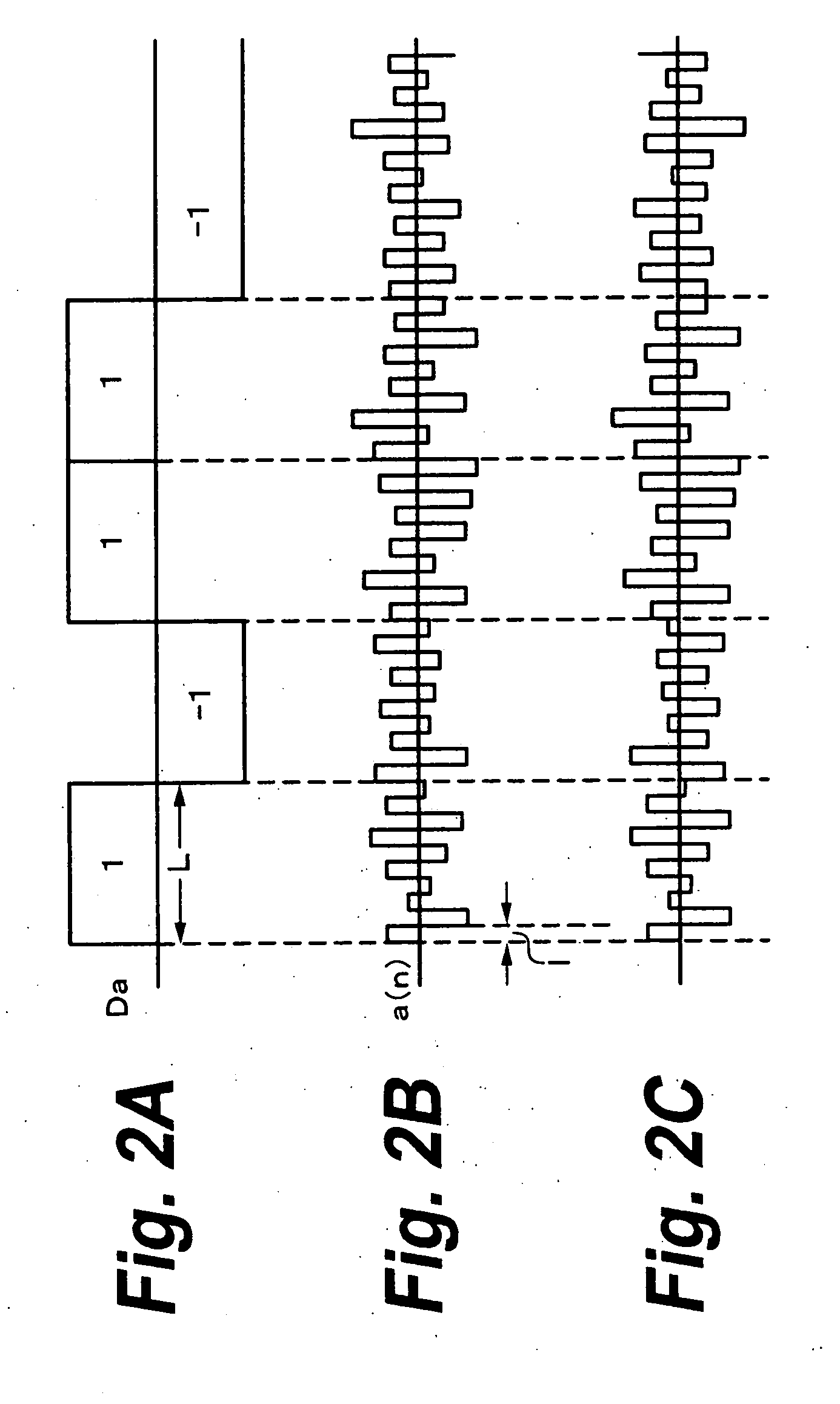
[0024] The data Da and Db are supplied to spreading units 2a and 2b in order to directly make spreading, respectively. A chaos spreading code a(n) is inputted to the spreading unit 2a from an input terminal 3a. The data Da and the chaos spreading code a(n) are multiplied in the spreading unit 2a. Another chao...


PUM


Abstract

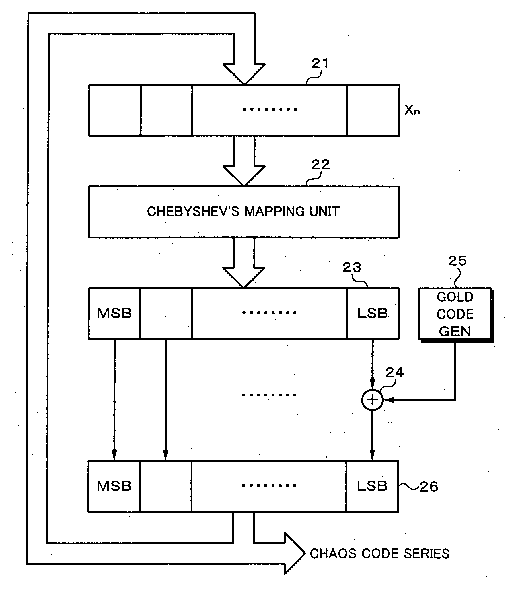
A chaos spreading code c(n) is inputted to a spreading unit 32. Data D1 and c(n) are multiplied in the spreading unit 32. A chaos spreading code d(n) is inputted to a spreading unit 42. Data D2 and d(n) are multiplied in the spreading unit 42. The chaos spreading codes c(n) and d(n) orthogonally cross each other. Outputs of the spreading units 32 and 42 are added by an adder 35 and transmitted through a transmitting unit 36 to a transmission path 38. By making an initial value which is set in a chaos sequence generator having a construction of a digital circuit different, the chaos spreading codes which orthogonally cross can be formed. Since the chaos spreading codes c(n) and d(n) orthogonally cross, an orthogonal modulating unit having a construction of an analog circuit for amplitude-modulating carriers which orthogonally cross can be made unnecessary and the construction can be simplified.

Description


Claims


Application Information

Patent Timeline
Owner NAT INST OF INFORMATION & COMM TECH
Learn More