
Systems and methods for eye-operated three-dimensional object location

a three-dimensional object and eye-operated technology, applied in the field of systems and methods for determining the three-dimensional location of objects, can solve the problems of only two-dimensional presentation, no natural means for exporting this information to the outside world, and the observer cannot see in the third dimension

Inactive Publication Date: 2006-09-21
LC TECH
View PDF7 Cites 98 Cited by
  • Summary
  • Abstract
  • Description
  • Claims
  • Application Information

AI Technical Summary

Benefits of technology

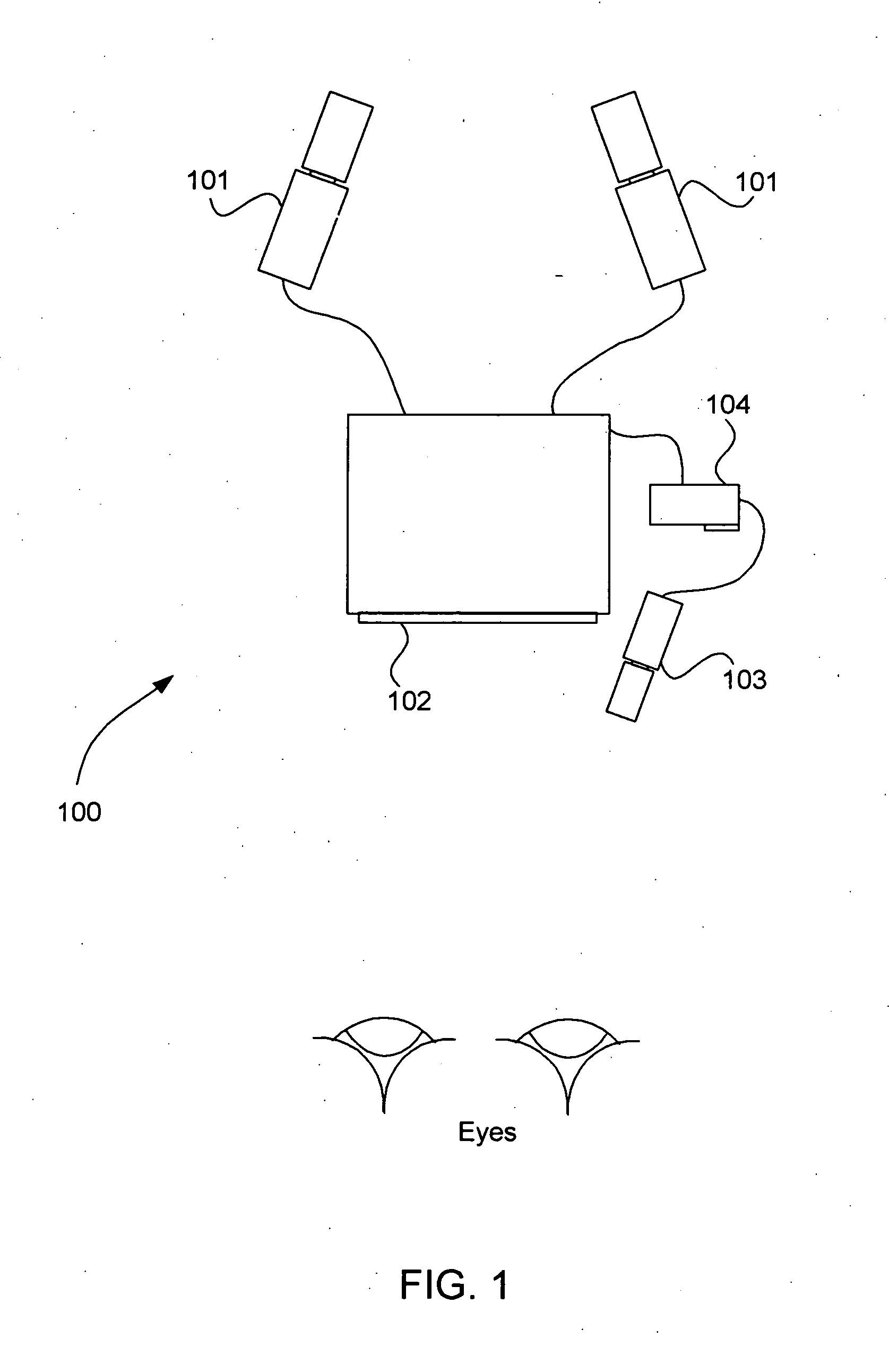
"The present invention is a system and method for determining the 3-D location of an object using a stereoscopic display, a gaze tracking system, and a processor. The system calculates the object's location based on the intersection of the first and second gaze lines from an observer's right and left eyes viewing the object on the stereoscopic display. The method also takes into account the locations and orientations of the two cameras used to capture the stereoscopic image. The technical effect of this invention is to provide a more immersive and realistic user experience for viewing and interacting with objects in a virtual or augmented reality environment."

Problems solved by technology

Though humans implicitly use 3-D object location information to guide the execution of their own physical activities, they have no natural means for exporting this information to the outside world.
As a result, a key limitation of almost all current remote display systems is that the presentation is only two-dimensional and the observer cannot see in the third dimension.

Method used


Image

  • Systems and methods for eye-operated three-dimensional object location
  • Systems and methods for eye-operated three-dimensional object location
  • Systems and methods for eye-operated three-dimensional object location

Examples


Embodiment Construction

[0016] It has long been known that the angular orientation of the optical axis of the eye can be measured remotely by the corneal reflection method. The method takes advantage of the eye's properties that the cornea is approximately spherical over about a 35 to 45 degree cone around the eye's optic axis, and the relative locations of the pupil and a reflection of light from the cornea change in proportion to eye rotation. The corneal reflection method for determining the orientation of the eye is described in U.S. Pat. No. 3,864,030, for example, which is incorporated by reference herein.

[0017] Generally, systems used to measure angular orientation of the optical axis of the eye by the corneal reflection method include a camera to observe the eye, a light source to illuminate the eye, and a processor to perform image processing and mathematical computations. An exemplary system employing the corneal reflection method is described in U.S. Pat. No. 5,231,674 (hereinafter the “'674 pa...


PUM


Abstract

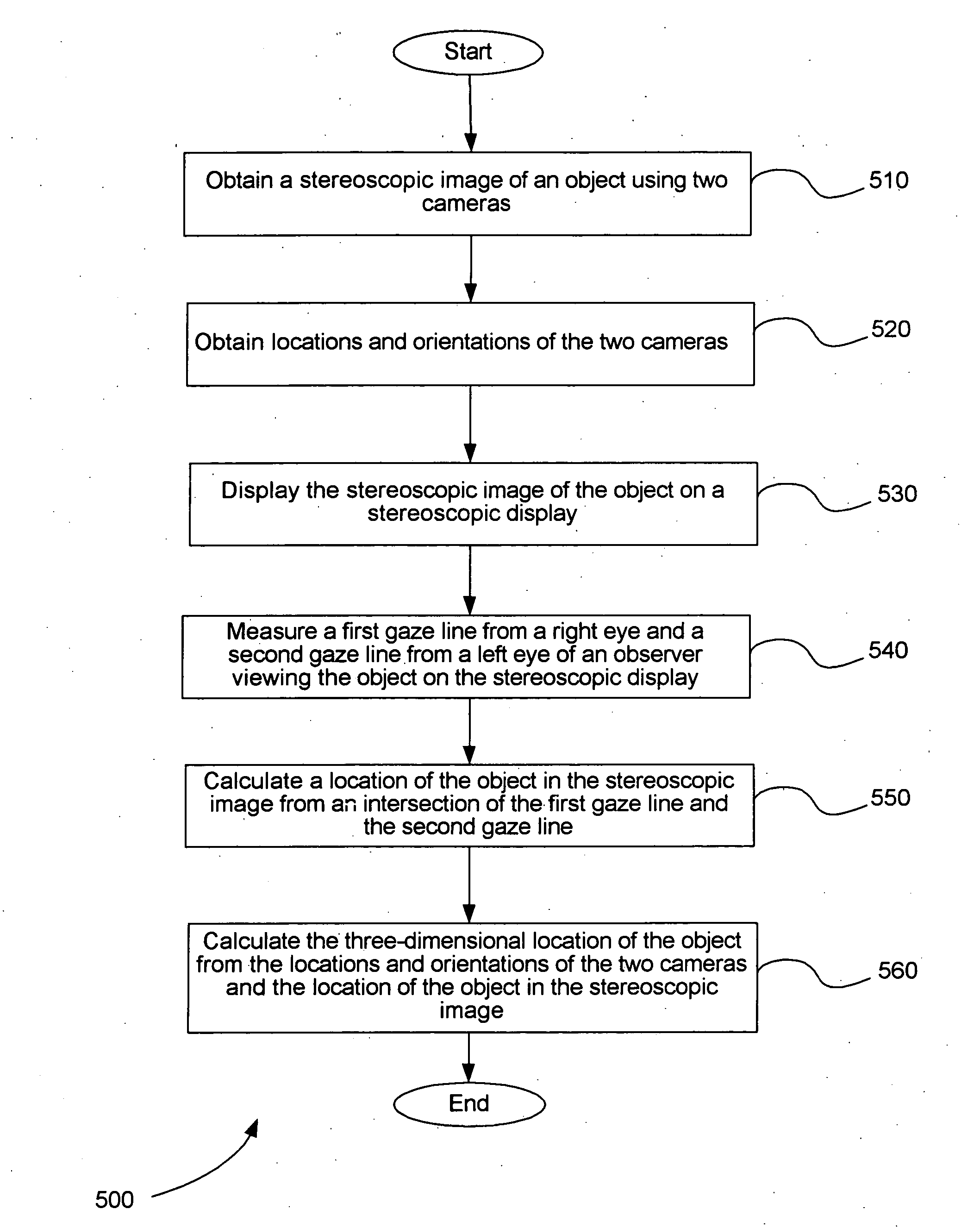
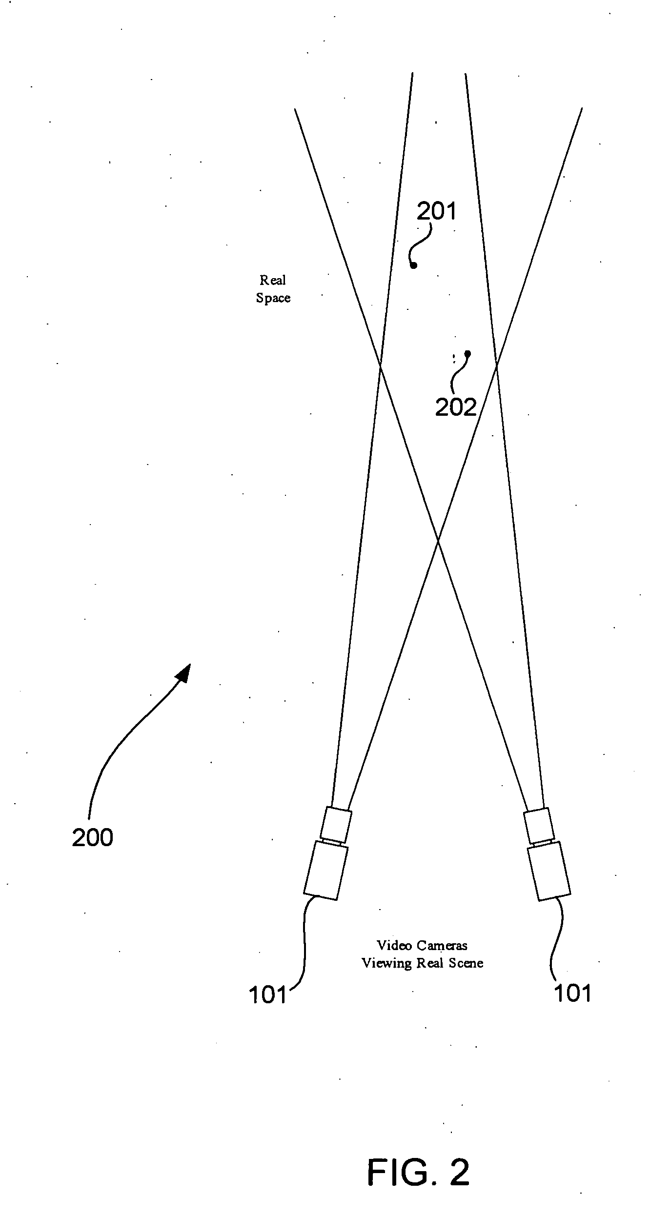
In an embodiment of the invention, a stereoscopic image of an object is obtained using two cameras. The locations and orientations of the two cameras are obtained. The stereoscopic image of the object is displayed on a stereoscopic display. A first gaze line from a right eye and a second gaze line from a left eye of an observer viewing the object on the stereoscopic display are measured. A location of the object in the stereoscopic image is calculated from an intersection of the first gaze line and the second gaze line. The three-dimensional location of an object is calculated from the locations and orientations of the two cameras and the location of the object in the stereoscopic image.

Description

[0001] This application claims the benefit of U.S. Provisional Application No. 60 / 661,962, filed Mar. 16, 2005, which is herein incorporated by reference in its entirety.BACKGROUND [0002] 1. Field of the Invention [0003] Embodiments of the present invention relate to systems and methods for determining the three-dimensional location of an object using a remote display system. More particularly, embodiments of the present invention relate to systems and methods for determining the binocular fixation point of a person's eyes while viewing a stereoscopic display and using this information to calculate the three-dimensional location of an object shown in the display. [0004] 2. Background of the Invention [0005] It is well known that animals (including humans) use binocular vision to determine the three-dimensional (3-D) locations of objects within their environments. Loosely speaking, two of the object coordinates, the horizontal and vertical positions, are determined from the orientati...

Claims


Application Information

Patent Timeline
Patent Type & Authority Applications(United States)
IPC IPC(8): G01C3/14H04N13/00G06K9/00
CPCG01C3/14G01C11/06G06T7/004H04N13/0239H04N13/0484G06T7/70H04N13/239H04N13/383
Inventor CLEVELAND, DIXONJOYCE, ARTHUR W. III
Owner LC TECH
Learn More