Refreshment cell

a technology of a refreshment cell and a compartment is applied in the field of refreshment cells, which can solve the problems of corresponding build-up of odors and increase the weight of the carrying along, so as to save time and effor

Inactive Publication Date: 2006-09-21
AIRBUS OPERATIONS GMBH
View PDF8 Cites 0 Cited by
  • Summary
  • Abstract
  • Description
  • Claims
  • Application Information

AI Technical Summary

Benefits of technology

[0014] The refreshment cell according to an exemplary embodiment of the invention may provide any passenger with the option to individually refresh oneself, in particular, independently of lavatories and toilets. The refreshment cell does not have the purpose of providing the passengers with an alter

Problems solved by technology

Most toilets and lavatories are heavily soiled during the course of a flight such that a corresponding build-up of odors occurs.
However, s

Method used


Image

  • Refreshment cell
  • Refreshment cell

Examples


Embodiment Construction

[0018] In the figures, identical and corresponding components are identified by the same reference symbols.

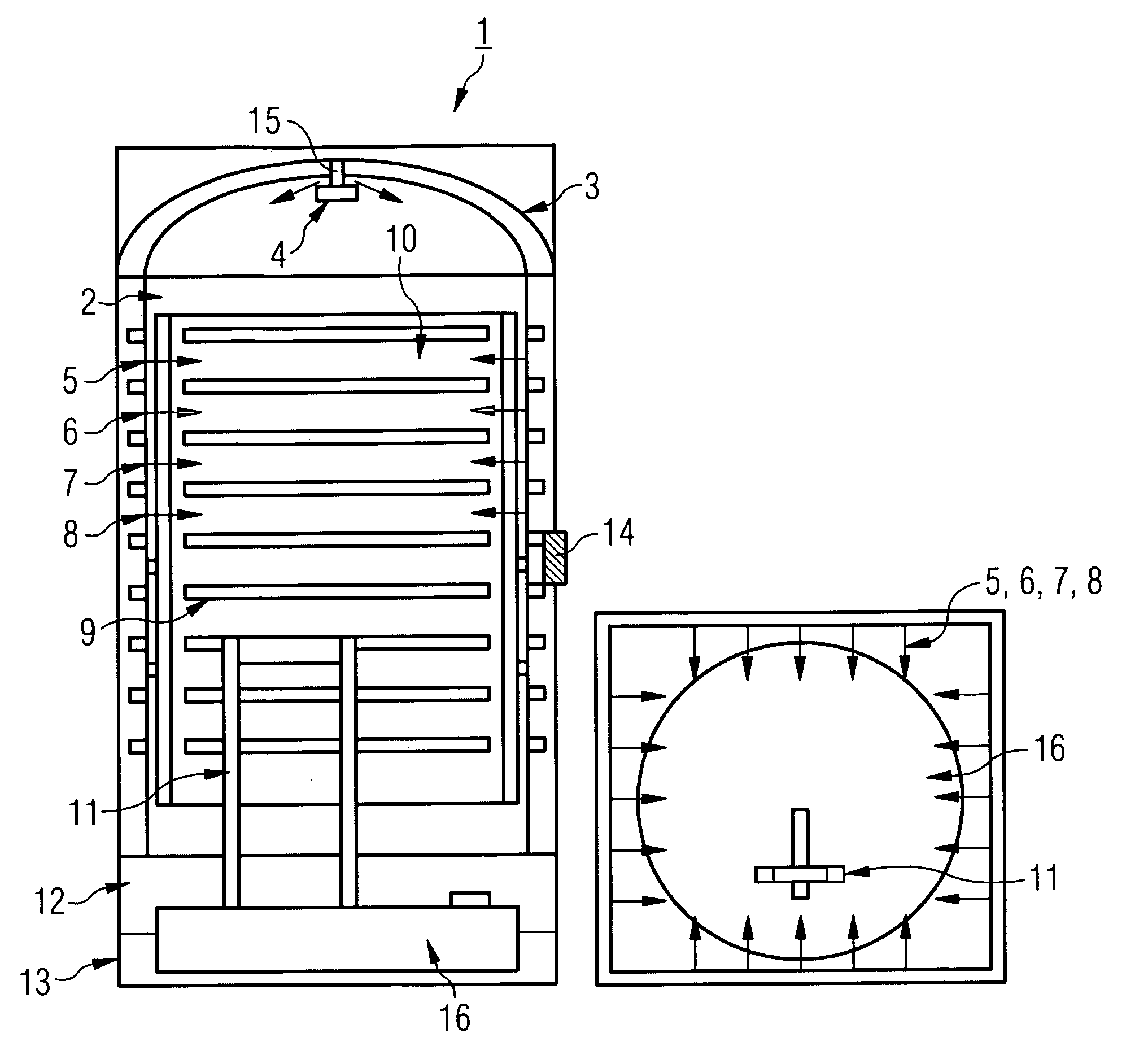
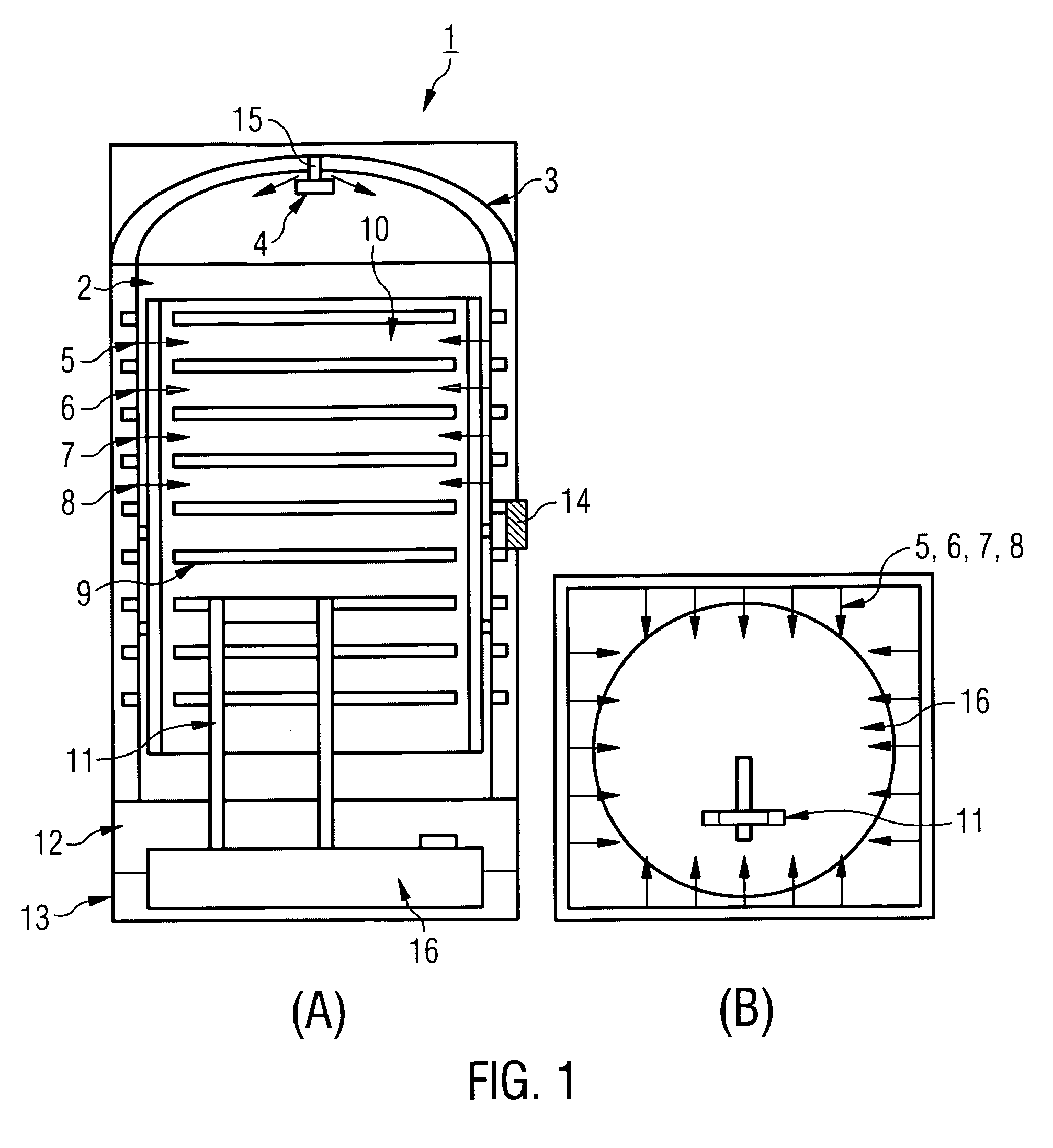
[0019]FIG. 1A shows a schematic cross-sectional representation of an exemplary embodiment of a refreshment cell 1. FIG. 1A shows that the refreshment cell 1 is realized, for example, in the form of a complete module / compartment analogous to an existing toilet unit.

[0020] The refreshment cell 1 shown in FIG. 1A has walls 2 in order to form a preferably enclosed space, in which a passenger can refresh oneself in an undisturbed fashion.

[0021]FIG. 1A shows that the refreshment cell 1 is provided with an air jet 4 that is arranged on the ceiling of a dome 3 of the refreshment cell 1 and serves for producing an air shower. The air jet 4 blows air into the interior of the refreshment cell from above.

[0022] On lateral regions of the refreshment cell 1 there is situated, for example, an air jet 5 in the form of an aromatizer in order to deliver aromatics into the refreshment cell 1....


PUM


Abstract

A refreshment cell for use in an aircraft cabin comprises an air shower in combination with a humidifying element.

Description

CROSS-REFERENCE TO RELATED APPLICATIONSBACKGROUND OF THE INVENTION [0001] This application claims the benefit of the filing date of U.S. Provisional Patent Application No. 60 / 644,965 filed Jan. 19, 2005, the disclosure of which is hereby incorporated herein by reference. [0002] The invention generally relates to a refreshment cubicle, particularly to a refreshment cell for use in an aircraft cabin. [0003] Genuine refreshment cubicles are usually not provided in aircraft cabins for business-class and economy-class passengers. Passengers of these classes currently utilize the toilets and the laboratories for refreshment purposes. Most toilets and lavatories are heavily soiled during the course of a flight such that a corresponding build-up of odors occurs. [0004] With respect to first-class and VIP customers, there exist various options for integrating a fresh water shower on board an aircraft. However, since these showers require that large quantities of fresh water be made available...

Claims


Application Information

Patent Timeline
IPC IPC(8): B64D13/00B64D11/00
CPCB64D11/02
Inventor BAUCH, ANNADOEBERTIN, OLIVERNIESIGK, ALEXANDERSCHOTTE, HERMANN
Owner AIRBUS OPERATIONS GMBH
Why Eureka
Try Eureka