Sliding swing device for mobile terminal

a mobile terminal and swing device technology, applied in the field of portable digital communication apparatuses, can solve the problems of inconvenient user viewing video or tv through a display device in the conventional portable communication apparatus, inconvenient body housing, and inconvenient user taking a photograph of a subject, so as to improve the assembly process of the mobile terminal and save assembly time. , the effect of slim and compa

Inactive Publication Date: 2006-09-21
SAMSUNG ELECTRONICS CO LTD
View PDF2 Cites 74 Cited by
  • Summary
  • Abstract
  • Description
  • Claims
  • Application Information

AI Technical Summary

Benefits of technology

[0014] It is still another aspect of the present invention to provide a sliding swing device that is slim and compact.
[0015] It is yet another aspect of the present invention to provide a sliding swing device, in which a housing of a mobile terminal can be separated and combined for the mounting of the sliding swing device, thereby improving the assembly process of the mobile terminal and saving assembly time.
[0016] It is yet one more aspect of the present invention to provide a sliding swing device which allows users to view a displayed screen (such as a screen in a TV or video view mode) at convenient positions by smoothly sliding and swinging.

Problems solved by technology

In conventional sliding-type portable communication apparatuses, however, a body housing can only slide in one direction and only has a single display device fixed to the body housing.
This makes it inconvenient for a user to take a photograph of a subject.
Furthermore, it is inconvenient for users to view video or TV through a display device in conventional portable communication apparatuses.

Method used


Image

  • Sliding swing device for mobile terminal
  • Sliding swing device for mobile terminal
  • Sliding swing device for mobile terminal

Examples


Embodiment Construction

[0038] The matters defined in the description such as a detailed construction and elements are provided to assist in a comprehensive understanding of the embodiments of the invention. Accordingly, those of ordinary skill in the art will recognize that various changes and modifications of the embodiments described herein can be made without departing from the scope and spirit of the invention. Also, descriptions of well-known functions and constructions are omitted for clarity and conciseness.

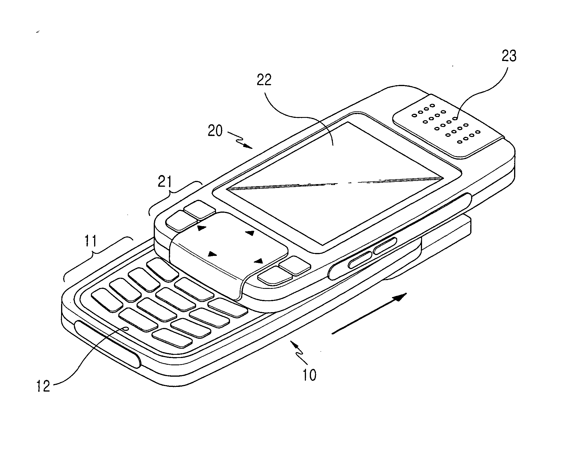
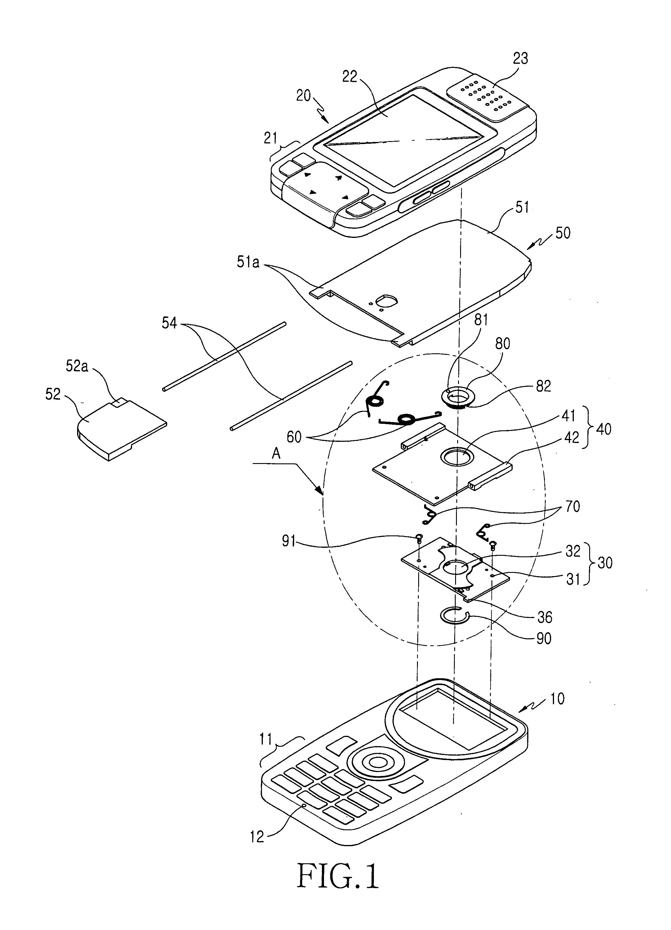
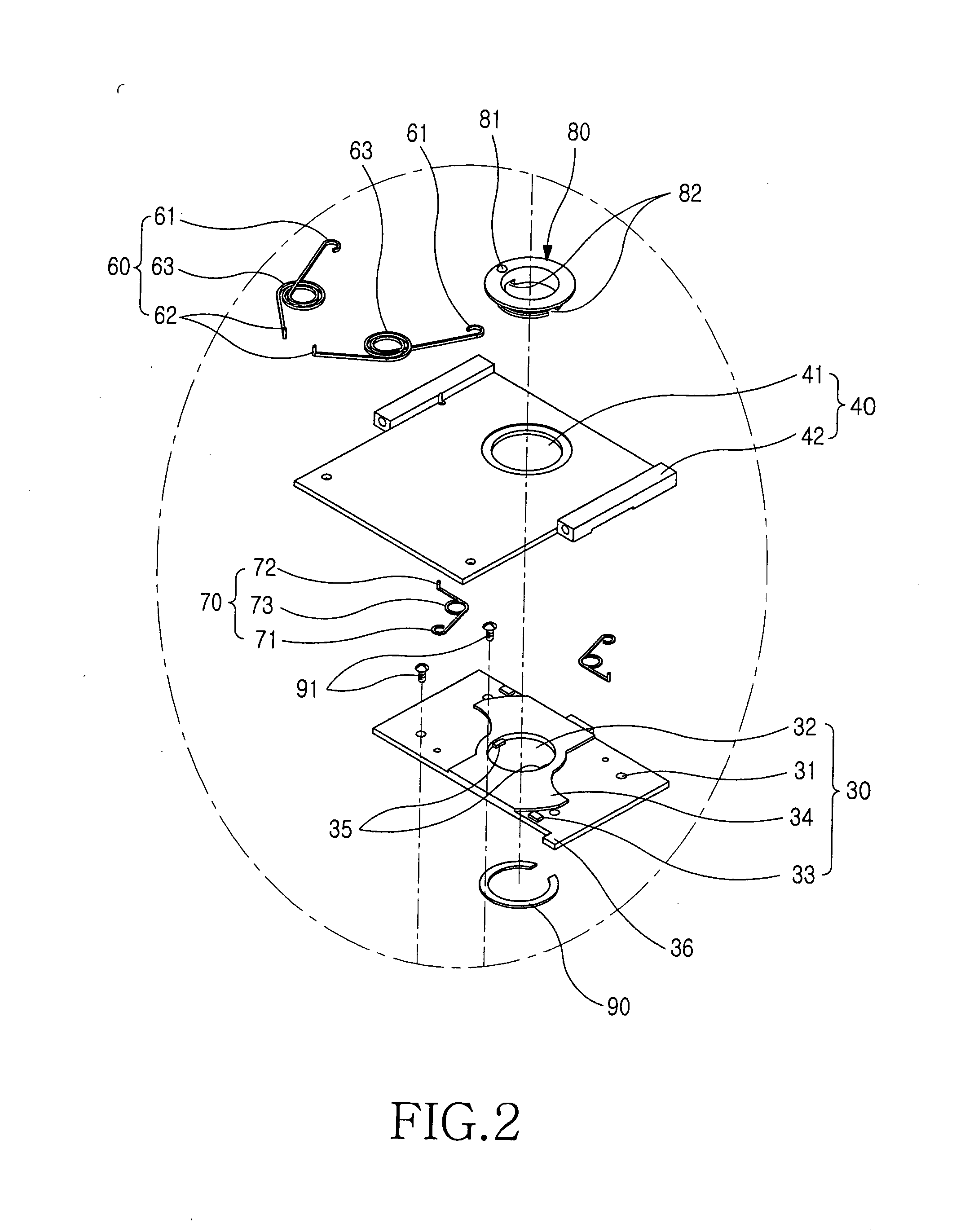
[0039] Referring to FIGS. 1, 2, and 5, a sliding swing device for a mobile terminal includes a base member 30, a sliding swing member 40, a guide member 50, a first force supplier 60, and a second force supplier 70. The base member 30 is combined with the sliding swing member 40 in a stacked fashion and is fixedly engaged with a main body housing 10. The sliding swing member 40 is combined with the base member 30 in a stacked fashion such that a sliding swing housing 20 slides from an initial p...


PUM


Abstract

A sliding swing device for a mobile terminal comprised of a main body housing and a sliding swing housing opened and closed in opposition to the main body housing is provided. The sliding swing device includes a base member, a sliding swing member, a guide member, a first force supplier, and a second force supplier. The sliding swing member is combined with the base member in a stacked fashion, slides from an initial position to an end position, and rotates at the initial position. The guide member is slidably combined with the sliding swing member. The first force supplier is provided between the sliding swing member and the guide member and supplies the guide member with force to semi-automatically slide from the initial position to the end position. The second force supplier is arranged under the first force supplier in a stacked fashion and supplies the sliding swing member with force to semi-automatically swing.

Description

CROSS-REFERENCE TO RELATED APPLICATIONS [0001] This application claims the benefit under 35 U.S.C. § 119(a) of an application entitled “Sliding Swing Device for Mobile Terminal” filed in the Korean Intellectual Property Office on Mar. 17, 2005 and assigned Ser. No. 2005-22063, the entire contents of which are incorporated herein by reference. BACKGROUND OF THE INVENTION [0002] 1. Field of the Invention [0003] The present invention generally relates to portable digital communication apparatuses, such as cellular phones, Personal Digital Assistants (PDAs), Hand Held Phones (HHPs), MPEG-1 Audio Layer 3 (MP3) phones, game phones, camera phones, Internet phones and combinations thereof. More particularly, the present invention relates to a sliding swing device for a mobile terminal that allows a user to conveniently view displayed information through a semi-automatic sliding / swing operation. [0004] 2. Description of the Related Art [0005] In general, a “portable communication apparatus” ...

Claims


Application Information

Patent Timeline
Patent Type & Authority Applications(United States)
IPC IPC(8): H04M1/00
CPCH04M1/0227H04M1/0233H04M1/0237B66C3/04B66C3/16
Inventor JEONG, DONGKANG, SUNG-ILL
Owner SAMSUNG ELECTRONICS CO LTD
Why Eureka
Try Eureka