
A Golf Club Head with a Face Insert

Active Publication Date: 2006-09-21
CALLAWAY GOLF CO
View PDF57 Cites 21 Cited by
  • Summary
  • Abstract
  • Description
  • Claims
  • Application Information

AI Technical Summary

Benefits of technology

[0012] The present invention overcomes the problems of the prior art by providing a golf club head that has a body with a striking plate insert composed of a substrate material and a nickel-iron alloy layer. This allows the golf club head of the present invention to have better inherent properties such as yield strength, tensile strength and hardness while also having more discretionary mass than conventional face insert golf club heads.

Problems solved by technology

However, the heat treatment process compromises the toughness of the material, where toughness is defined as the resistance of the material to fracture under loading.
Thus, even heat treated, high strength, metastable titanium alloys have limited application as face inserts due to inferior fracture properties.
Some alloy materials that have desired inherent properties such as yield strength, tensile strength and hardness often have high densities, which limit the utilization of such materials in golf club heads.

Method used


Image

  • A Golf Club Head with a Face Insert
  • A Golf Club Head with a Face Insert
  • A Golf Club Head with a Face Insert

Examples


Embodiment Construction

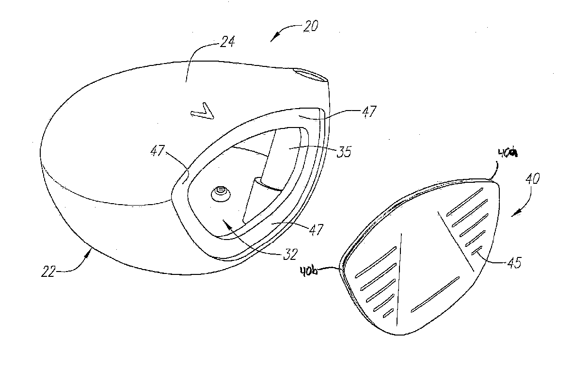
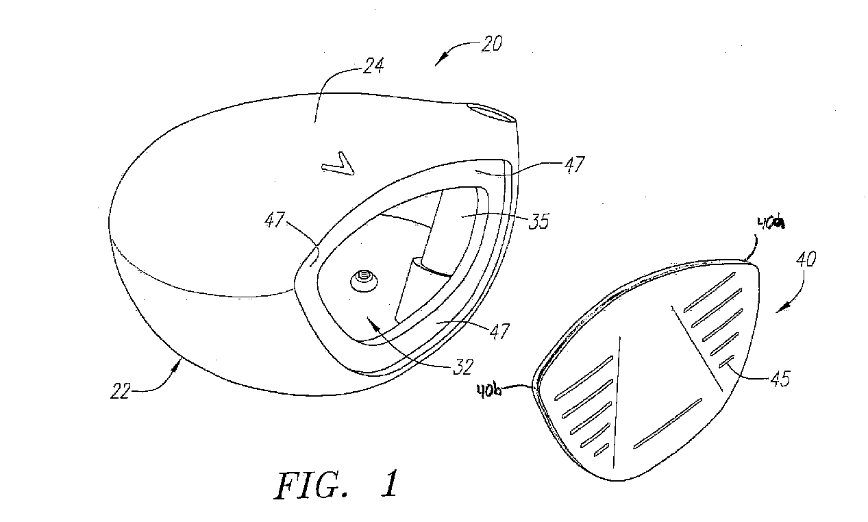
[0014]FIG. 1 is an exploded view of the components of a preferred embodiment of a golf club head.

[0015]FIG. 2 is a front view of a golf club head.

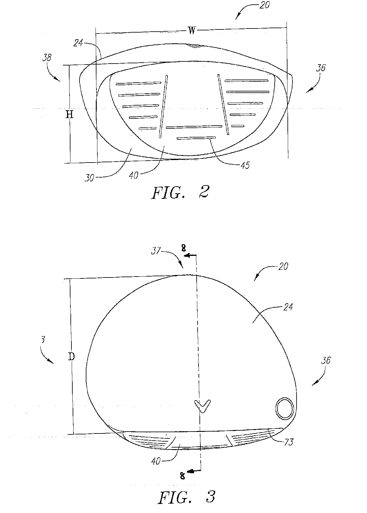
[0016]FIG. 3 is a top plan view of a golf club head.

[0017]FIG. 4 is a side view of the heel end of a golf club head.

[0018]FIG. 5 is side view of the toe end of a golf club head.

[0019]FIG. 6 is a bottom plan view of a golf club head.

[0020]FIG. 7 is a rear view of a golf club head.

[0021]FIG. 8 is a cross-sectional view along line 8-8 of FIG. 3.

[0022]FIG. 9 is an enlarged isolated view of the striking plate insert.

DETAILED DESCRIPTION OF THE INVENTION

[0023] As shown in FIGS. 1-8, the golf club head is generally designated 20. The golf club head 20 of FIGS. 1-8 is a driver, however, the golf club head may alternatively be a fairway wood. The golf club head 20 has a body 22 that is preferably composed of a metal material such as titanium, titanium alloy, steel alloys such as stainless steel, magnesium alloys, aluminum alloys, magnesium...


PUM


Abstract

A golf club head (20) having a body (22) with a front wall (30) with an opening (32) and a striking plate insert (40) is disclosed herein. The striking plate insert (40) has a substrate base layer (40a) and a second layer (40b). The second layer (40b) is preferably composed of a nickel-iron alloy material. The golf club head (20) preferably has a volume between 200 cubic centimeters and 600 cubic centimeters. The golf club head (20) preferably has a mass between 140 grams and 215 grams.

Description

BACKGROUND OF THE INVENTION [0001] 1. Field of the Invention [0002] The present invention relates to a golf club head. More specifically, the present invention relates to a golf club head with a face insert. [0003] 2. Description of the Related Art [0004] High performance drivers employ relatively thin, high strength face materials. These faces are either formed into the curved face shape then welded into a driver body component around the face perimeter, or forged into a cup shape and connected to a body by either welding or adhesive bonding at a distance offset from the face of up to 0.75 inch. In a popular embodiment of the sheet-formed face insert driver, the weld between the formed face insert and the investment cast driver body is located on the striking face, a small distance from the face perimeter. It is common practice for the face insert to be of uniform thickness and to design the surrounding driver body component to be of equal thickness. In this way there is continuity...

Claims


Application Information

Patent Timeline
IPC IPC(8): A63B53/04
CPCA63B53/0466A63B2053/0412A63B2053/0408A63B2209/023A63B2209/00A63B2053/0416A63B53/0412A63B53/0408A63B53/0416
Inventor DESHMUKH, UDAY V.
Owner CALLAWAY GOLF CO
Learn More