
Antistatic structure for optical disc device

an optical disc and anti-static technology, applied in the field of anti-static structure, can solve the problems of increasing the number of components and production costs, the static electricity generated on the spindle motor mb>1/b> not being communicated or badly communicated with the metal sheet, and the system is apt to be unstable. , to achieve the effect of reducing the number of components

Inactive Publication Date: 2006-09-21
LITE ON TECH CORP
View PDF9 Cites 4 Cited by
  • Summary
  • Abstract
  • Description
  • Claims
  • Application Information

AI Technical Summary

Benefits of technology

[0010] One object of the present invention is to provide an antistatic structure for an optical disc device, capable of reducing the number of components so as to attain to the best antistatic effect.
[0011] For achieving the object mentioned above, the present invention proposes an antistatic structure for an optical disc device. An optical pick-up unit module of an optical disc device is installed on a chassis and the chassis is movably installed in a lower cover. The antistatic structure is installed on the chassis and includes at least one upper connection portion and at least one lower connection portion. The upper connection portion contacts with the optical pick-up unit module and the lower connection portion contacts with the lower cover; thereby the static electricity generated on the optical pick-up unit module is smoothly conducted to the lower cover through the upper and the lower connection portions so as to effectively attain the antistatic protection object.
[0013] Besides, the upper connection portion installed on the chassis can be directly correspondingly got in touch with the relative components on the optical pick-up unit module, such as a turntable to allow the static electricity generated by the components on the module to be conducted directly to the chassis through the upper connection portion without by means of the transmission of another component so as to allow the statistic generated by the relative components of the optical pick-up unit module being transmitted smoothly to the chassis.
[0014] According to the preferred embodiment of the present invention, the front end of the upper connection portion is bended in an angle to allow the area of the front end contacting with the optical pick-up unit module being effectively increased.

Problems solved by technology

However, in an optical pick-up unit module used in optical disc devices, many components such as a spindle motor M1, pick-up unit P and stepping motor for driving the optical pick-up unit P all have a possibility to generate static electricity so that the a system is apt to be unstable, even to crash or power failure thereof is easy to happen.
However, such a design would increase the number of components and the production costs.
But, this will cause the static electricity generated on the spindle motor M1 not be communicated or badly communicated with the metal sheet 102 installed on the optical pick-up unit module 10.
Therefore, the conventional antistatic structure is not an ideally designed structure.

Method used


Image

  • Antistatic structure for optical disc device
  • Antistatic structure for optical disc device
  • Antistatic structure for optical disc device

Examples


Embodiment Construction

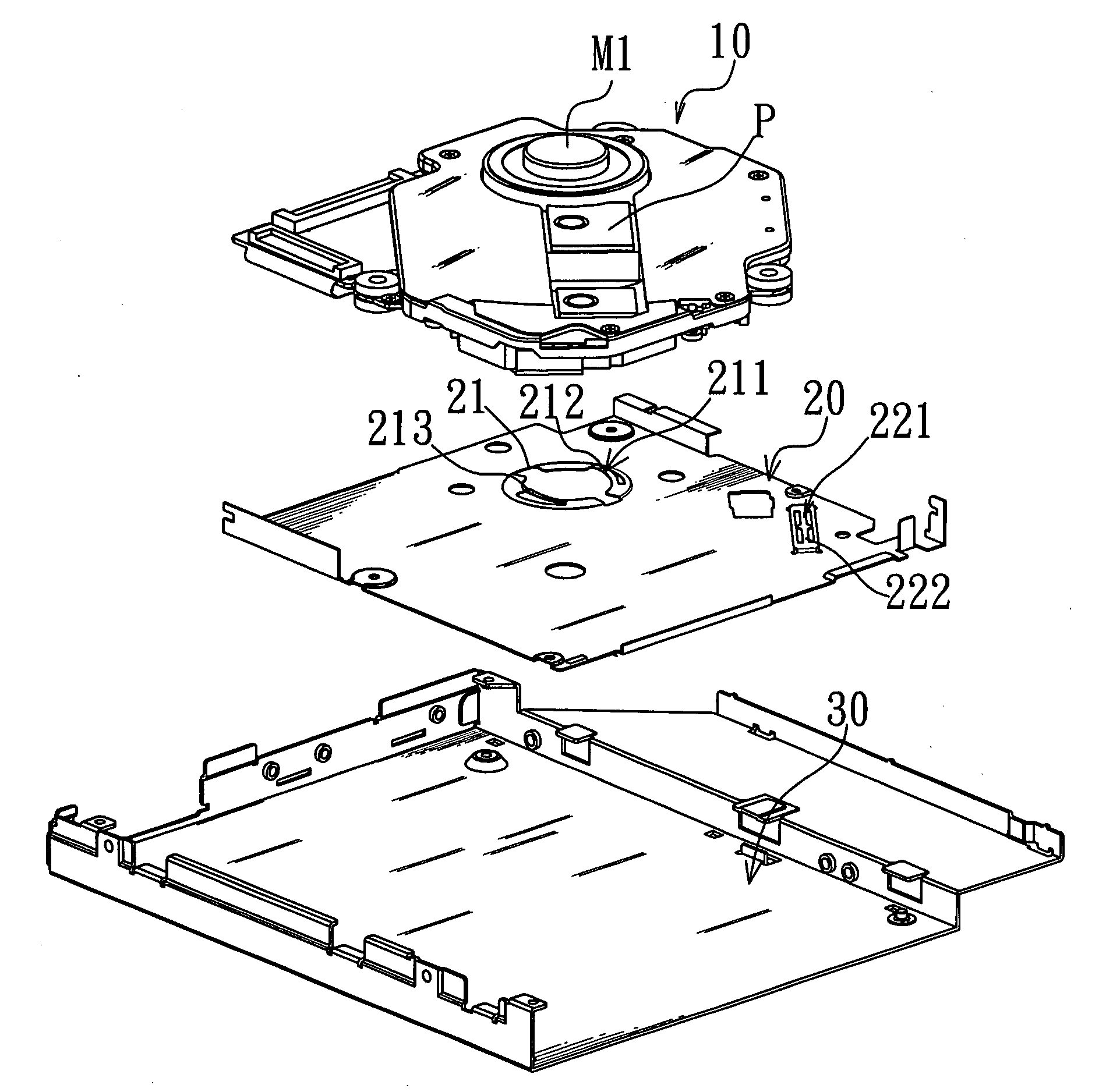
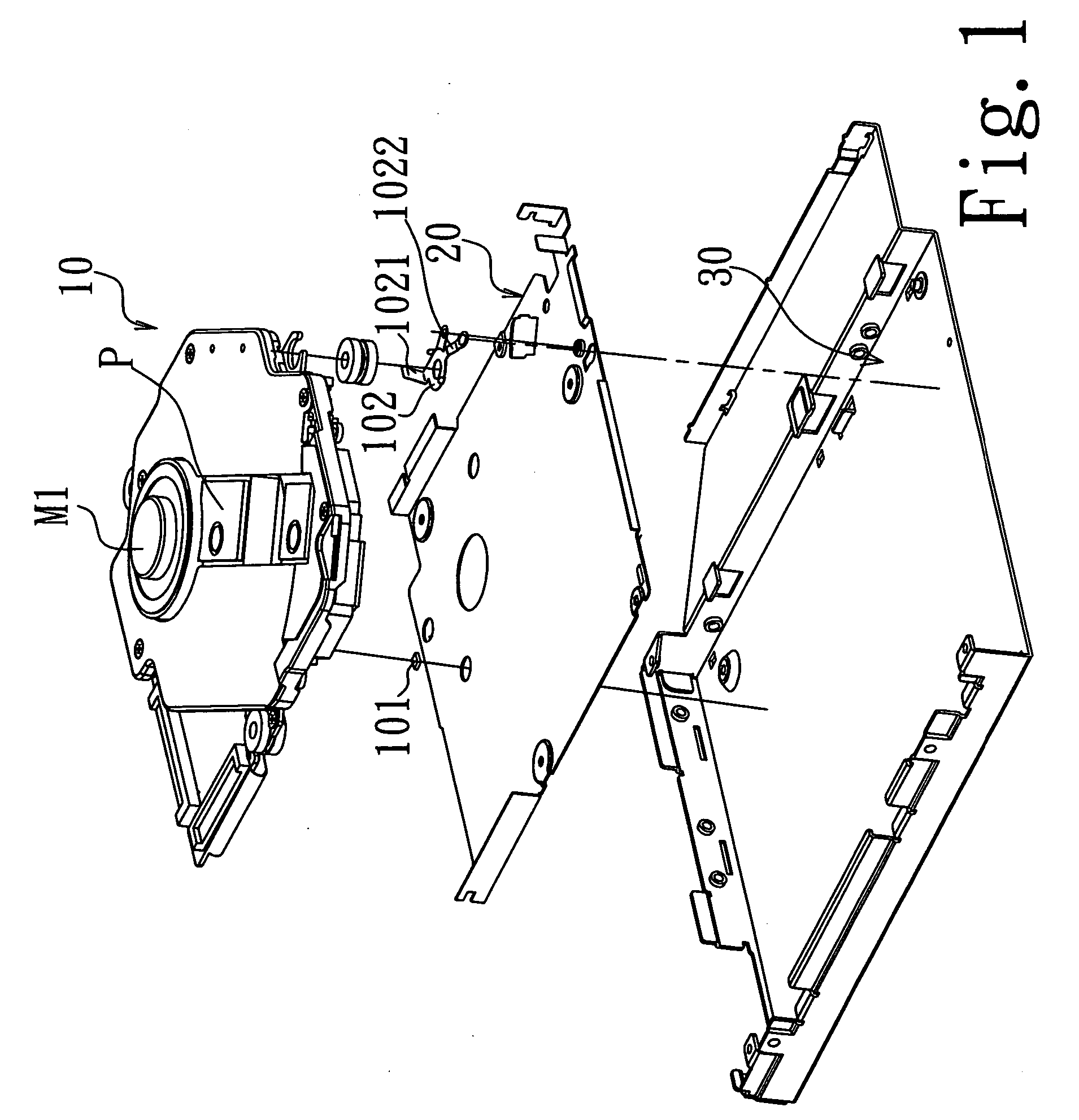
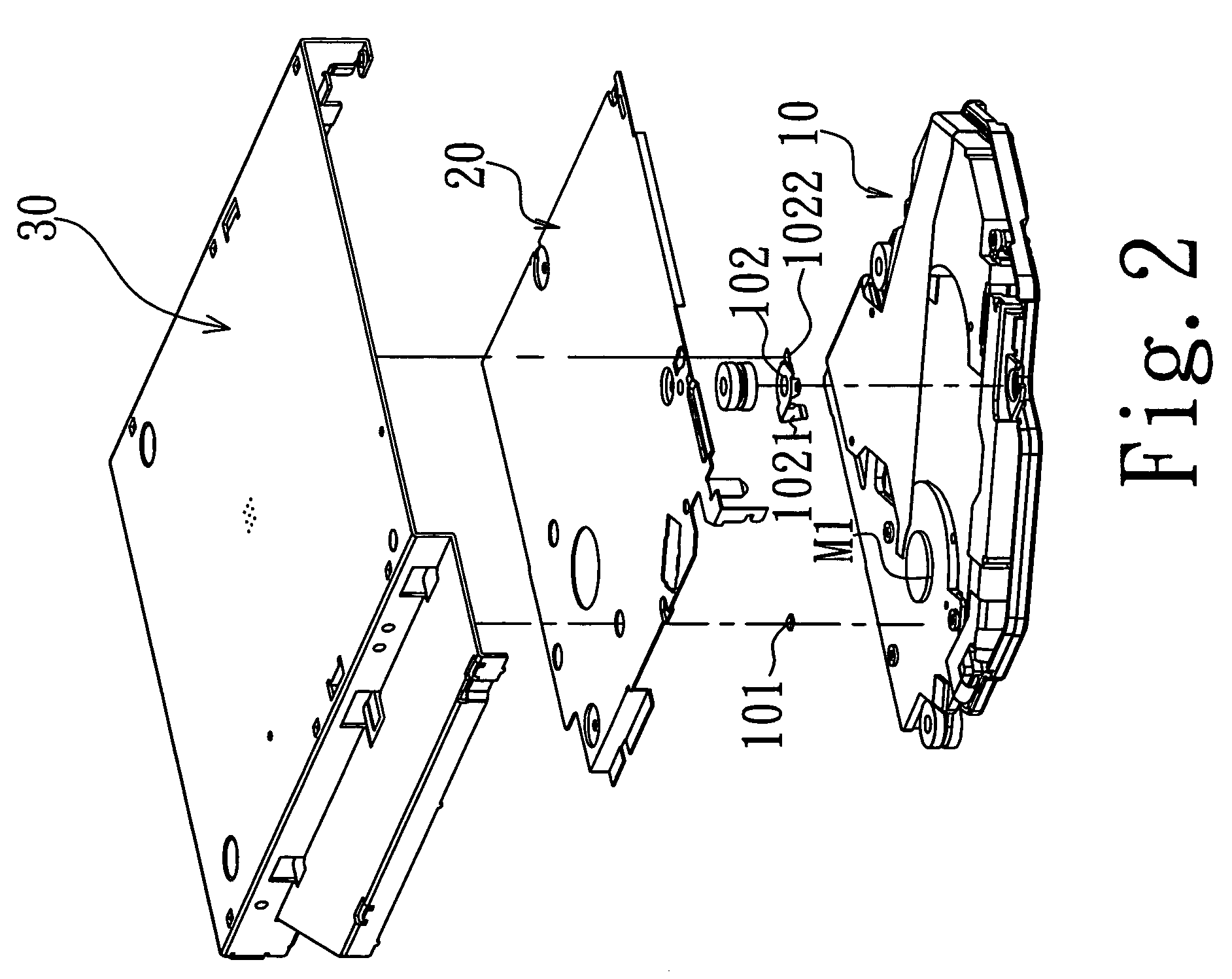
[0031] Please refer to FIGS. 3 and 4. FIG. 3 is a prospective top view, showing an antistatic structure of one preferred embodiment according to the present invention; and FIG. 4 is a prospective bottom view, showing the chassis in the antistatic structure shown in FIG. 3. An antistatic structure of an optical disk device of one preferred embodiment according to the present invention is installed on a chassis 20 which is used to shield and protect an optical pick-up unit module 10 to allow the optical pick-up unit module 10 to be electrically conductive with a lower cover 30.

[0032] The antistatic structure comprises at least one flexible upper connection portion 211 and at least one flexible lower connection portion 221; in which the upper connection portions 211 are disposed at the inside of a through hole 21 on the chassis 20 and each of which has an upper connecting arm 212 extending from the rim of the through hole 21 in a direction toward the optical pick-up unit module 10. A ...


PUM

PropertyMeasurementUnit
flexibleaaaaaaaaaa
antistaticaaaaaaaaaa
contact areaaaaaaaaaaa

Abstract

The present invention relates to an antistatic structure for an optical disc device. An optical pick-up unit module of an optical disk device is installed on a chassis and the chassis is movably installed in a lower cover of the device. Furthermore, the antistatic structure includes at least one upper connecting portion capable of contacting with the optical pick-up unit module and at least one lower connecting portion capable of contacting with the lower cover. Whereby, the static electricity generated by the optical pick-up unit module can be conducted to the lower cover through the upper and lower connecting portions so as to attain the antistatic discharge (ESD) protection effectively.

Description

[0001] This Non-provisional application claims priority under 35 U.S.C. §119(a) on Patent Application No(s). 094108238 filed in Taiwan, Republic of China on Mar. 17, 2005, the entire contents of which are thereby incorporated by reference. 1. FIELD OF THE INVENTION [0002] The present invention relates to an antistatic structure, and more particularly to an antistatic structure for an optical disc device. 2. DESCRIPTION OF RELATED ART [0003] With the arrival of the information age, an optical disc device has already developed mature gradually. However, in an optical pick-up unit module used in optical disc devices, many components such as a spindle motor M1, pick-up unit P and stepping motor for driving the optical pick-up unit P all have a possibility to generate static electricity so that the a system is apt to be unstable, even to crash or power failure thereof is easy to happen. For this reason, the optical disc device must pass an electrostatic discharge (ESD) protection test so...

Claims


Application Information

Patent Timeline
Patent Type & Authority Applications(United States)
IPC IPC(8): G11B7/00
CPCG11B7/1201G11B7/121
Inventor CHEN, JUNG FULEE, IN SHUENTSENG, CHUN JENHSIEH, CHIH CHUNGHUANG, JENG WEN
Owner LITE ON TECH CORP
Features
  • Generate Ideas
  • Intellectual Property
  • Life Sciences
  • Materials
  • Tech Scout
  • Unparalleled Data Quality
  • Higher Quality Content
  • 60% Fewer Hallucinations
Learn More