Support member and system for affixation to bed rails or bed frame

a technology for supporting members and bed frames, which is applied in the direction of sofas, adjustable height tables, bedstands, etc., can solve the problems of cumbersome installation and maintenance, increased cross member costs, and added to the overall weight of the structure, so as to prolong the life of the bed frame itself, reduce the effect of rigidity

Inactive Publication Date: 2006-09-28
FINGER LAKES INTPROP
View PDF10 Cites 10 Cited by
  • Summary
  • Abstract
  • Description
  • Claims
  • Application Information

AI Technical Summary

Benefits of technology

[0020] With the universal cross member of the present invention, the need for a support glide or caster to support the cross member is, in almost all instances, eliminated such that the cross member does not require any support that contacts the floor beneath the cross member. Accordingly, the need for some initial setting and constant readjustment of the height of such a support component is eliminated along with the consequent problems associated therewith and previously described. In addition, due to the unique construction of the present universal cross member, the gauge of the steel used can still be a relatively light gauge and not a heavy steel component.
[0042] In the preferred embodiment, the slide end is simply snapped into the rail connection and thus can be readily installed by a person setting up the bed without the need for any tools such that the time required for assembly of the bed is greatly reduced and can be carried out by the user in the home. The actual connection between the slide connector and the rail connector is preferably such that the snap-in procedure is simple to join those components together, without the use of any tools, however, the completed connection cannot easily be detached so that the connection is sure and positive and, preferably, cannot be disconnected without the use of tools. Thus, once installed, the universal cross member of the present invention is solidly affixed to the particular side rail and is not easily dislodged but can only be removed by quite deliberate positive action by the user. As such, no tools are necessary to carry out the assembly of the bed when the rail connector of the present invention is installed on the side rails.

Problems solved by technology

Such wooden slats were strong enough to provide the necessary support to the box spring, however, they were generally troublesome, somewhat weak and were cumbersome to install and maintain in place, and required screws for assembly, particularly when moving the bed from one location to another.
Obviously, the steel cross members could be constructed of very heavy gauge steel so that adequate support could be provided for the box spring and mattress, however, the use of heavy gauge steel increases the cost of the cross member and additionally, adds to the overall weight of the structure.
Therefore, although constructed of steel, the present cross members alone are not sufficient to provide the necessary amount of support for the box spring and mattress.
If, on the other hand, the length of the glide assembly is too long, it causes the cross member to bow upwardly.
In either case, the result is undesirable and can cause structural damage to the cross member and possibly to the box spring.
The need for the adjustment is paramount in that the headboard and footboard, if there is one, is not a standard industry height above the floor and thus, the height of the frame and the side rails off the floor will differ from bed to bed so that a fixed height glide assembly would not be suitable to fit all beds universally.
Where the floor is covered, for example, with carpeting, the dragging causes twisting of the glide assembly and can easily lead to a breaking of the leg from the cross member and / or ever damage to the box spring.
Added to that weakness, is the fact that many cross members are coupled together at the center point between the two side rails, that is, the cross member is generally extended in two sections inwardly from the side rails and is coupled together at or near the center of the span between the side rails by some clamp or other coupling device to compensate for the varying widths of the headboards and footboards.
Thus, the center of the span between the supporting side rails is already a vulnerable spot where the cross member is weak, however, adding to that weakness is the use of a coupling at that center spot where the two individual cross member are joined together by a clamp.
In short, the glide assembly that supports the cross member is in a most vulnerable position with respect to being damaged or to damaging the cross member and the box spring by the user moving it from one location to another or by simply having the height adjustment incorrectly set.
Obviously for the user or installer, this is a severe problem as it creates the necessity to obtain another bed rail or support system as the breaking of a leg is generally not repairable since the components are stamped metal parts that are riveted together.
Another problem exists in the construction of a cross member in that the actual width or span between the side rails may have a variance and thus there may need to make an adjustment in the length of the cross member to insure that it properly aligns with the particular fitting or bracket in the side rails.
The difficulty is particularly significant where the cross member is assembled by fitting into brackets or the like in the side rails as the length must be accurate to make the proper fitting possible.
Thus, presently there are many ways to attach the cross members to a side rail that are non-standard devices.
However, again, the center of the cross member is already the weakest area of the cross member and the addition of a sliding connection at that point adds to the weakness of the cross member.

Method used


Image

  • Support member and system for affixation to bed rails or bed frame
  • Support member and system for affixation to bed rails or bed frame
  • Support member and system for affixation to bed rails or bed frame

Examples


Embodiment Construction

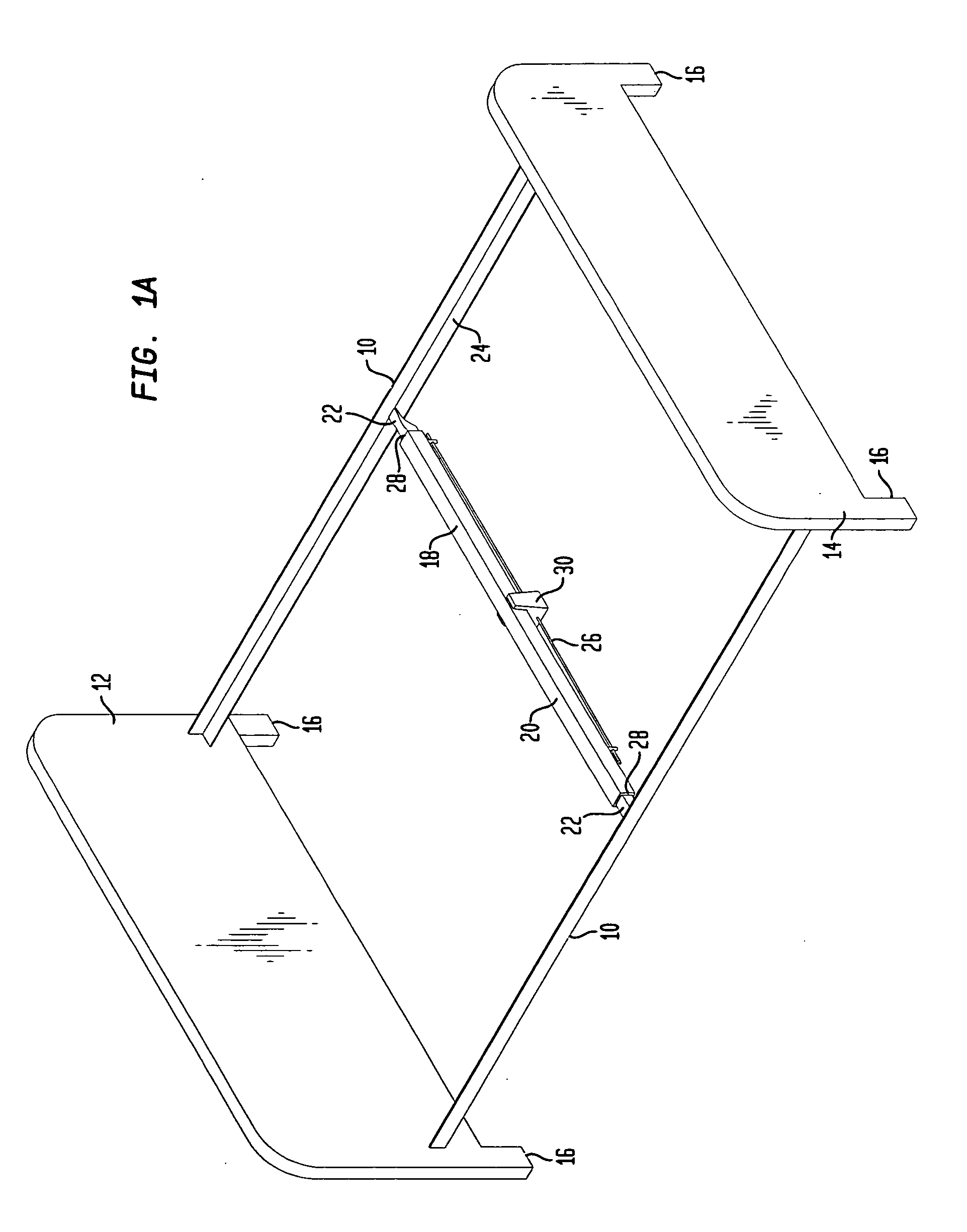
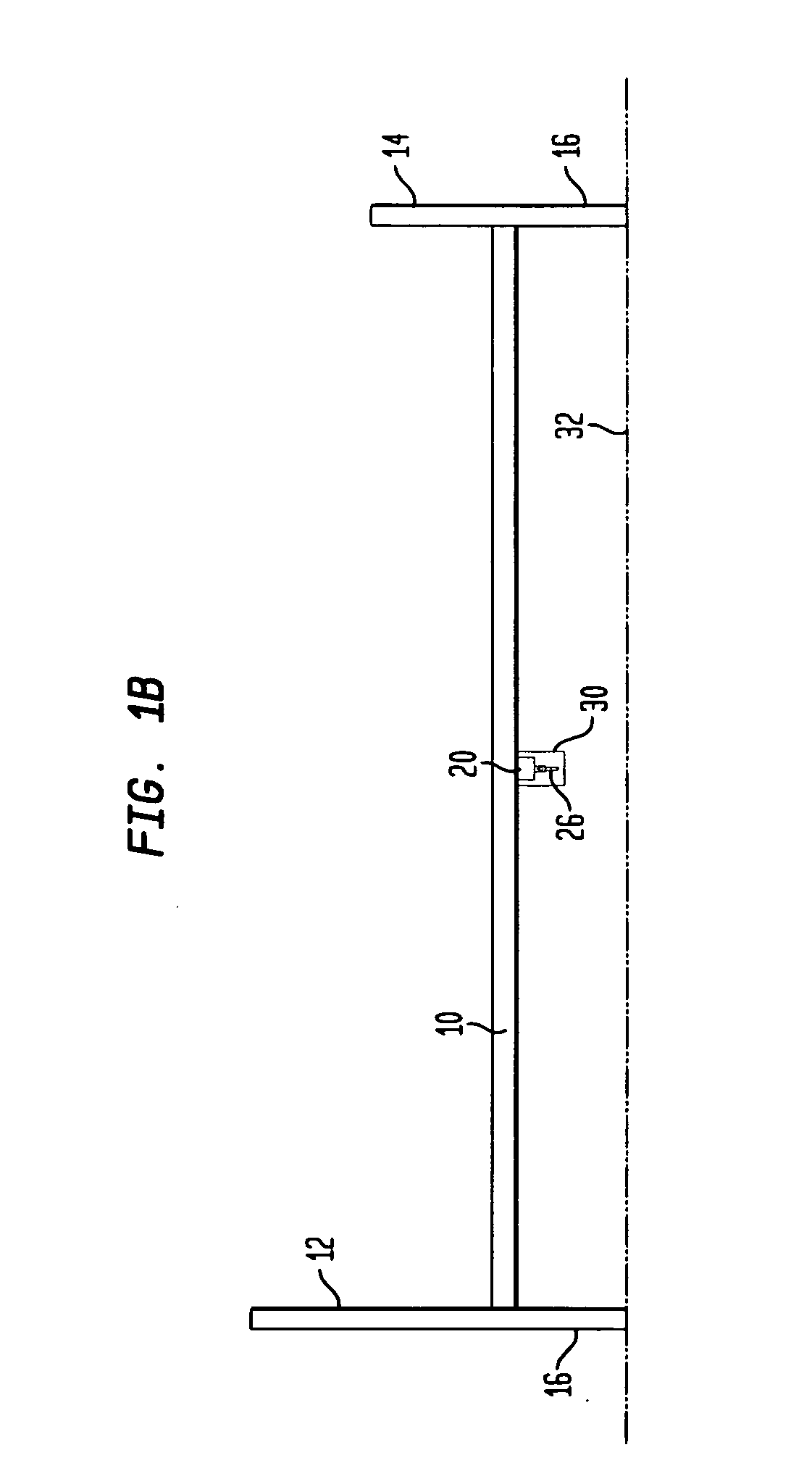
[0074] Referring now to FIG. 1A, there is shown a perspective view of a completed bed assembly and which includes conventional components such as side rails 10 that are positioned parallel to each other and spaced apart a predetermined distance depending upon the type of box spring and mattress to be used with the bed assembly. At one end of the side rails 10, there is a headboard 12 generally affixed in normal means to the side rails 10 and at the opposite ends of the side rails 10, there is a footboard 14 that is, again, affixed to the side rails 10 in any conventional manner.

[0075] As will be noted, the typical bed assembly may or may not include both a headboard and a footboard, and those components are both shown for convenience in illustrating the present invention. It should be noted, however, that the headboard 12 and the footboard 14 both are provided with legs 16 and which support the entire bed assembly on the surface of a floor. The particular length of the legs 16 is n...


PUM


Abstract

A cross member that can be used with a bed frame or bed rails to provide support for a box spring and mattress. The cross member is attachable to the side rail of the bed by a snap-in system where the ends of the cross member are comprised of slide ends that interfit into receptacles located along the side rails. A leg is used to support a bed frame member that is self adjusting by a mechanism that can be unlocked by a person to drop the leg downwardly by gravity to contact the floor and is then lockable in that extended length.

Description

REFERENCE TO RELATED CASES [0001] This patent application is a Continuation-In-Part application based upon and claiming priority of U.S. Patent Application, U.S. Ser. No. 09 / 518,320, filed Mar. 3, 2000 and entitled UNIVERSAL TENSION SPRING SUPPORT MEMBER FOR BED RAILS OR BED FRAME.BACKGROUND [0002] This invention relates generally to a support assembly for a frame or rail assembly to connect a headboard and a footboard and, ultimately to support a mattress and box spring, and, more particularly, to an improved universal cross member support for a bed frame or bed rails. [0003] Bed frames or bed rails are widely used to provide a support for the box spring and mattress and are of a relatively straightforward construction comprising a rectangular or square frame. In the case of bed rails, there are normally side rails that are wooden, rolled formed metal or angle iron and which connect to a headboard and a footboard. The side rails, the headboard and the footboard are interconnected s...

Claims


Application Information

Patent Timeline
Patent Type & Authority Applications(United States)
IPC IPC(8): A47C19/02A47C19/00A47C23/00
CPCA47C19/02A47C19/025A47C19/027
Inventor POLEVOY, RICHARD S.RYAN, HOWARD SCOTTCARLSON, PAUL ERIC
Owner FINGER LAKES INTPROP
Why Eureka
Try Eureka