Apparatus for multi-axis rotation and translation

a multi-axis rotation and translation technology, applied in the direction of mechanical control devices, manual control with multiple controlling members, manual control with single controlled members, etc., can solve the problems of limited load-carrying capacity, poor positioning accuracy, and the architecture of parallel 6dof manipulators is more complex

Inactive Publication Date: 2006-09-28
HAYES MATTHEW JOHN D +2
View PDF7 Cites 26 Cited by
  • Summary
  • Abstract
  • Description
  • Claims
  • Application Information

AI Technical Summary

Problems solved by technology

Typically each joint has its own actuator which provides a relatively large range of motion and relatively simple control but have generally poor positioning accuracy and very limited load-carrying capacity (as the majority of the load capacity is taken up by actuators themselves).
Conversely, parallel 6DOF manipulators are architecturally more complex because they are formed with several closed kinematic loops, typically two or more kinematic chains that connect a moving platform to a base, where one joint in the chain is actuated and the other joints are passive.
Their limitations are that they are highly coupled, more difficult to control and have very limited ranges of motion.
While these platforms have excellent structural stiffness, they have the inherent drawback that the degrees of freedom are highly coupled.
Thus, when the platform nears its limit of motion in one direction (or degree of freedom), it loses its ability to move in other directions (or other degrees of freedom).
A further disadvantage of the Stewart-type platform is that they often rely upon hydraulic actuators, especially in large scale platforms where the actuators must be able to generate large forces to support gravitational loads.
Unfortunately, this axis must be within the angular limits of the universal joint, typically ±30°.
While this platform can move with six degrees of freedom, it is very complex, requires a lot of power and is only capable of unlimited roll.

Method used


Image

  • Apparatus for multi-axis rotation and translation
  • Apparatus for multi-axis rotation and translation
  • Apparatus for multi-axis rotation and translation

Examples


Embodiment Construction

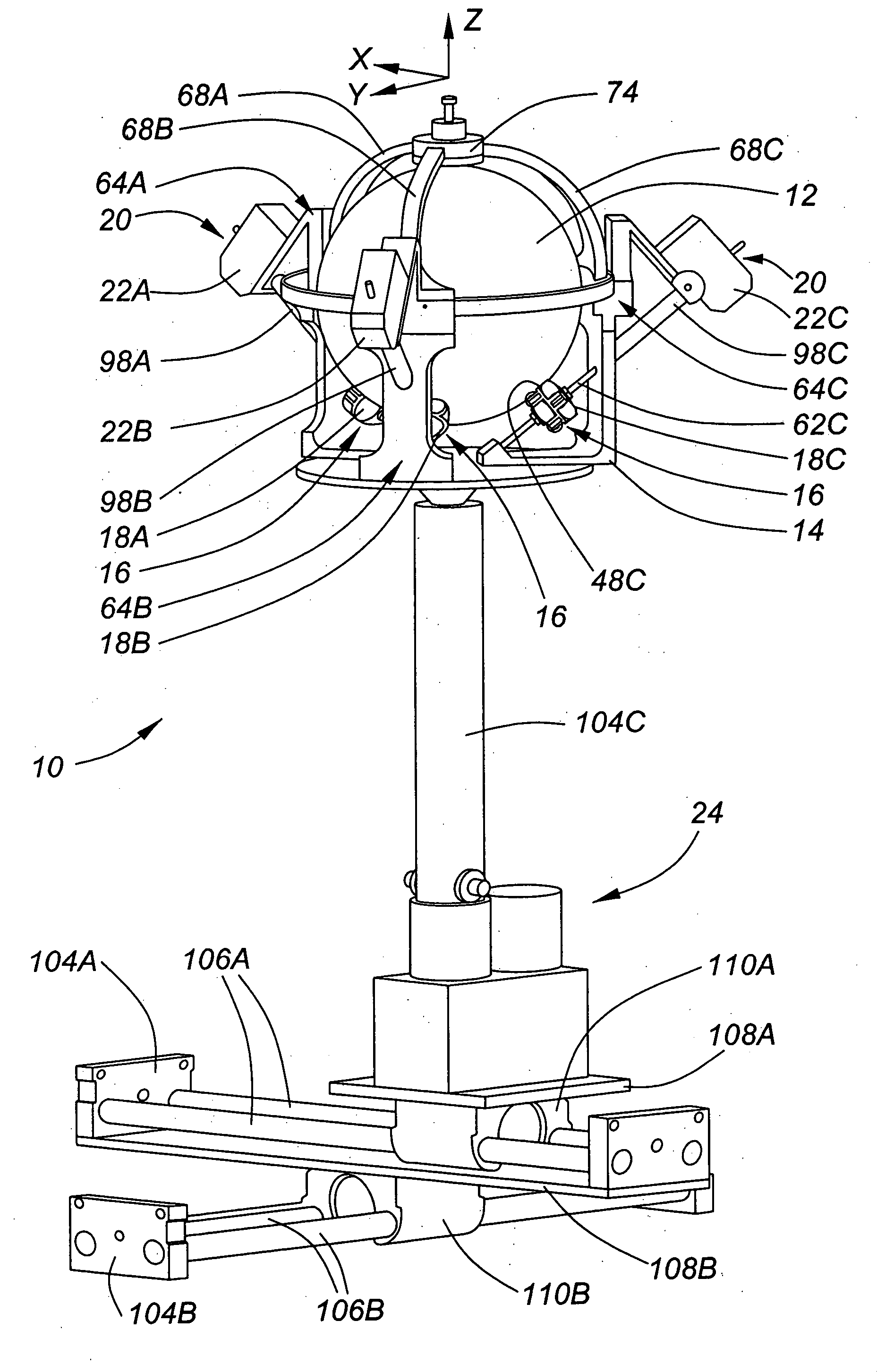
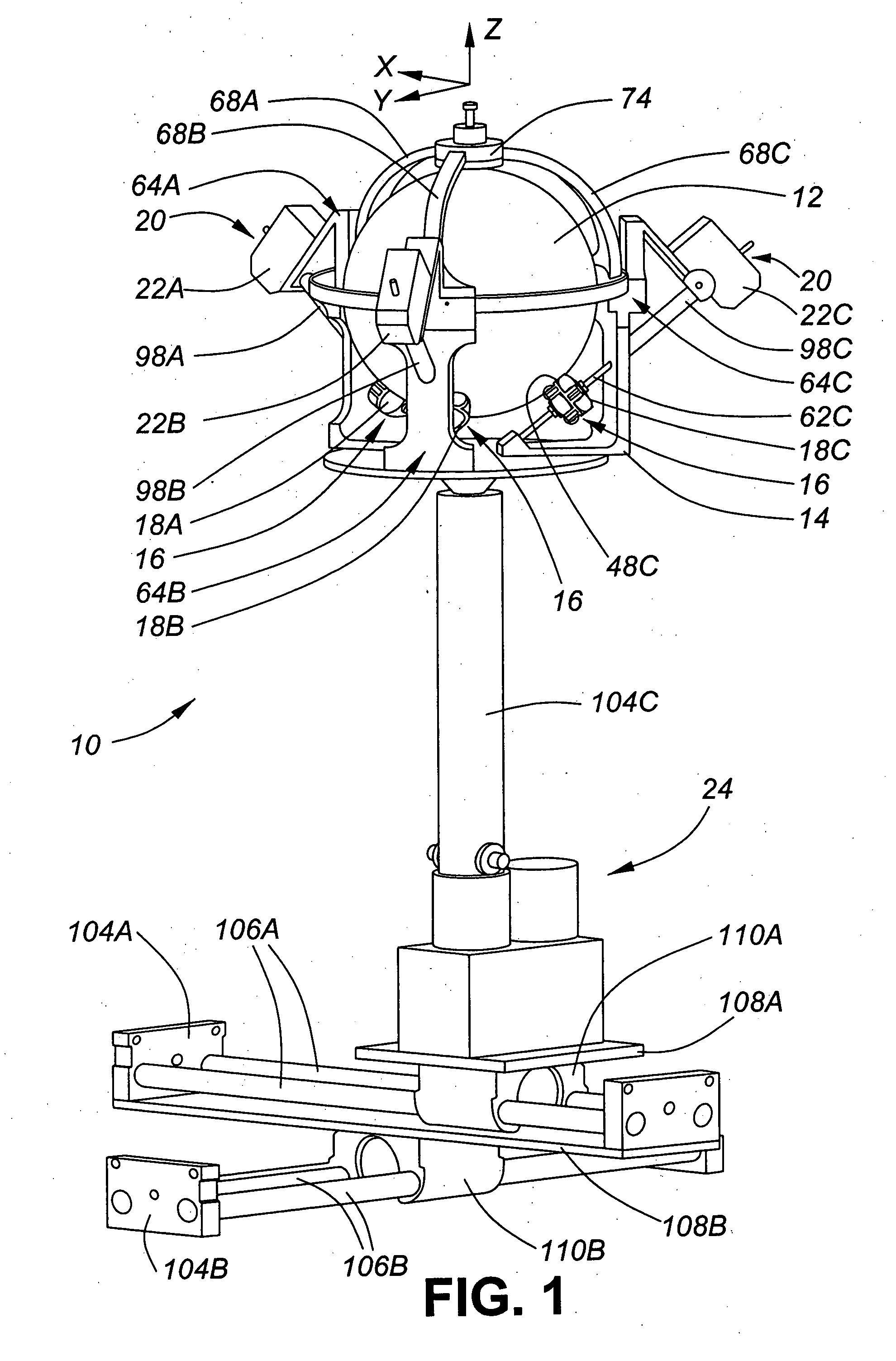
[0021] An embodiment of the invention will be described in reference to X, Y and Z axes as indicated in FIGS. 1 and 2. The term “roll” refers to rotation about the X-axis, the term “pitch” refers to rotation about the Y-axis and the term “yaw” refers to rotation about the Z-axis (vertical).

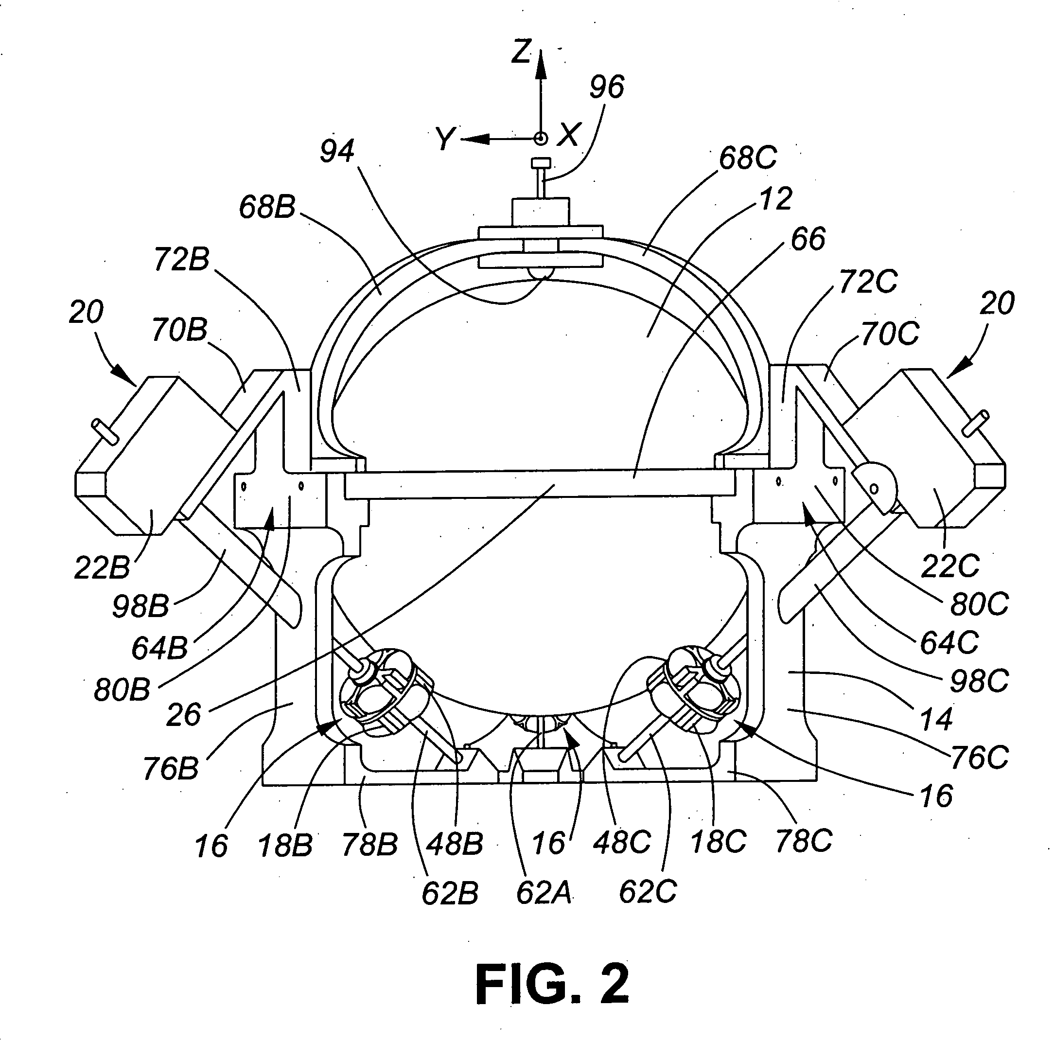
[0022] Referring to FIGS. 1 and 2, there is illustrated an apparatus 10 for multi-axis rotation and translation comprising a spherical body 12 supported by a frame 14, a plurality of roller assemblies 16, a plurality of actuators 20 for driving the roller assemblies 16, respectively, and translation means 24. The Z-axis passes through the geometric center 26 of the spherical body 12. The actuators 20 may be of any suitable configuration but as shown are three variable speed DC motors 22A, 22B and 22C.

[0023] In the embodiment shown in FIGS. 1 and 2, the roller assemblies 16 comprise three omni-wheels 18A, 18B and 18C. It will be understood by those skilled in the art that there are other configur...


PUM


Abstract

An apparatus for multi-axis rotation and translation comprises a spherical body, a plurality of roller assemblies each engaging the outer surface of the spherical body, a plurality of actuators for driving said roller assemblies, a frame for supporting the plurality of roller assemblies and the plurality of actuators and translation means for translating the frame along each of three orthogonal axes. The actuators are selectively operated to drive the roller assemblies thereby imparting unlimited angular displacement to the spherical body and rotating the spherical body about any axis passing through its geometric center. The translation means may be operated to translate said spherical body along at least one of said three orthogonal axes. The apparatus is particularly applicable to use as a manipulator with six degrees of freedom (unlimited rotational displacement and translational displacement limited only by the boundaries of the workspace).

Description

FIELD OF THE INVENTION [0001] The present invention relates to an apparatus for multi-axis rotation and translation of a spherical body. BACKGROUND OF THE INVENTION [0002] Manipulators capable of motion in three linear and three angular directions singularly or in any combination are often referred to as “six degrees of freedom” (6DOF) manipulators. They have many applications such as motion simulator platforms, sensor calibration tables, precision aiming devices, machining operations, and material handling. These manipulators have different architectures and can be categorized into serial and parallel configurations. [0003] Serial 6DOF manipulators, such as a six-axis wrist-partitioned serial manipulator, have a relatively simple kinematic structure and do not have any closed kinematic loops. Typically each joint has its own actuator which provides a relatively large range of motion and relatively simple control but have generally poor positioning accuracy and very limited load-car...

Claims


Application Information

Patent Timeline
Patent Type & Authority Applications(United States)
IPC IPC(8): B25J18/00
CPCB25J9/023Y10T74/20305B25J17/0275
Inventor HAYES, MATTHEW JOHN D.LANGLOIS, ROBERT G.FRALICK, MICHAEL
Owner HAYES MATTHEW JOHN D
Why Eureka
Try Eureka