
Separable paper stripping device

Inactive Publication Date: 2006-09-28
YU CHEN HSIU MAN
View PDF8 Cites 6 Cited by
  • Summary
  • Abstract
  • Description
  • Claims
  • Application Information

AI Technical Summary

Benefits of technology

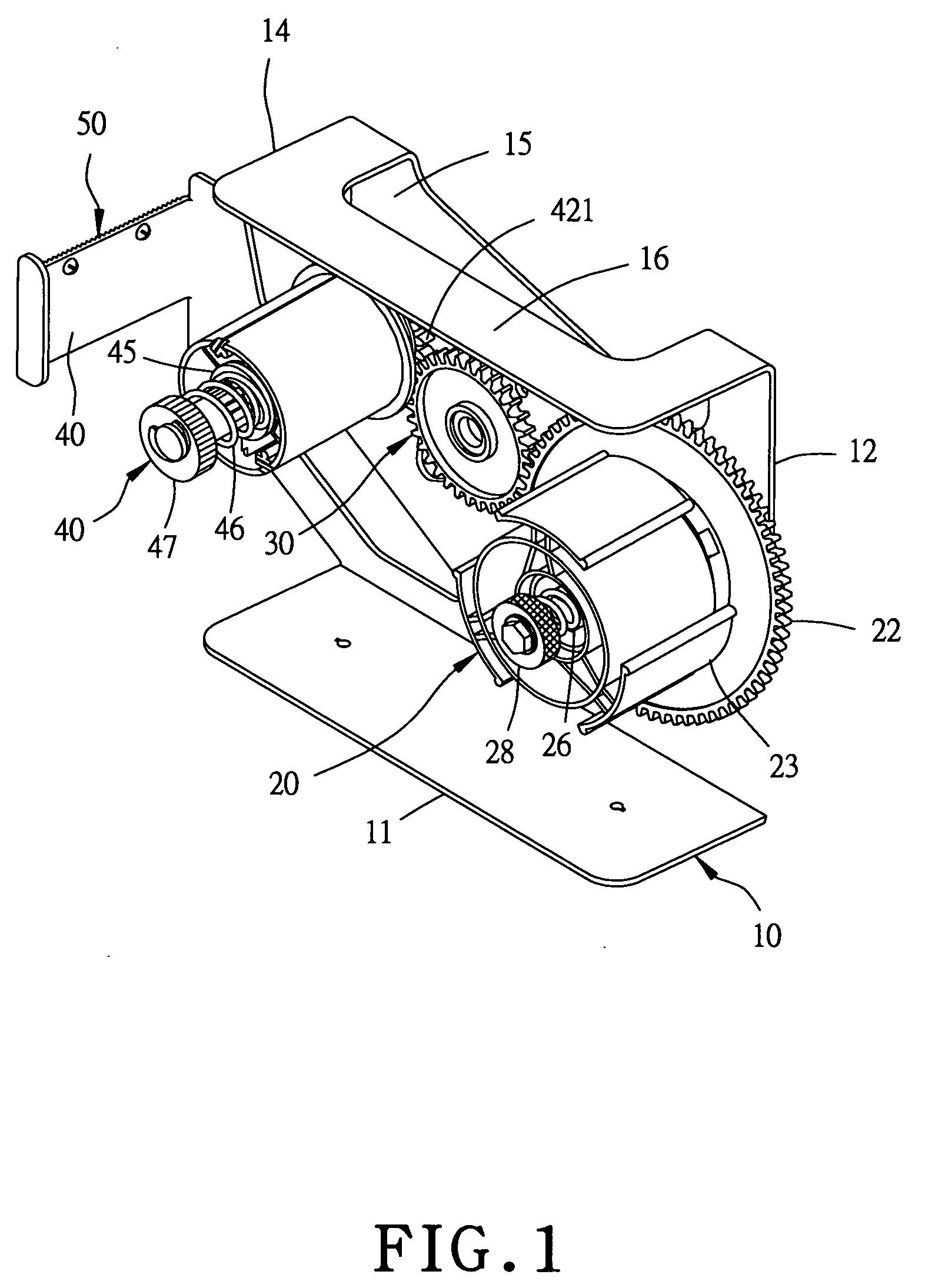
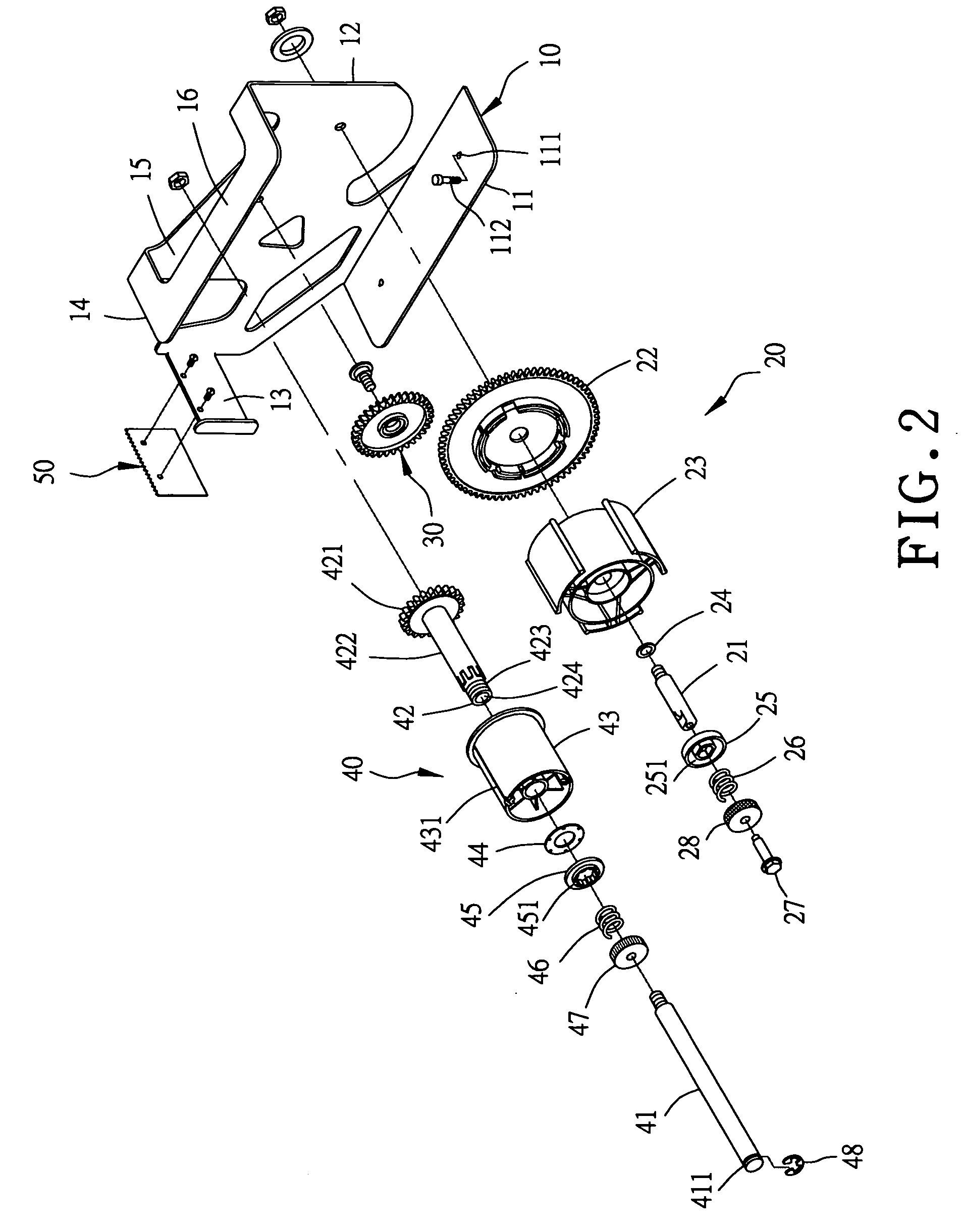
[0006] The objective of the invention is to offer a separable paper-stripping device including a base formed with a first wall plate and a second wall plate. The first wall plate is axially assembled thereon with a paper-roll holder, an idle gear and a separable-paper holder, and the second wall plate has a cutting member fixed thereon. The paper-roll holder is provided with a first gear engaged with the idle gear for actuating the second gear of the separable-paper holder to rotate. After a separable-paper roll is fitted on the paper-roll holder and the separable paper stripped from the separable-paper roll has its end connected with the separable-paper holder, the sticking paper and the separable paper of the separable-paper roll can be easily separated from each other by pulling forward the end of the stripped sticking paper, and the stripped separable paper can be rolled up by the separable-paper holder, easy and convenient in use.

Problems solved by technology

The separable paper and the sticking paper of a separable-paper roll have to be manually separated from each other first whenever the sticking paper is to be used for pasting, resulting in inconvenience in use.
However, a conventional separable paper-stripping device is complicated in structure and it is provided with no device for controlling the tightness in rotation of a separable-paper roll for rolling up separable paper.
Thus, the separable-paper roll is likely to become loosened and rotates randomly, and sticking paper may be pulled out too long or rotated backward and pasted randomly, causing much trouble in use.

Method used


Image

  • Separable paper stripping device
  • Separable paper stripping device
  • Separable paper stripping device

Examples


Embodiment Construction

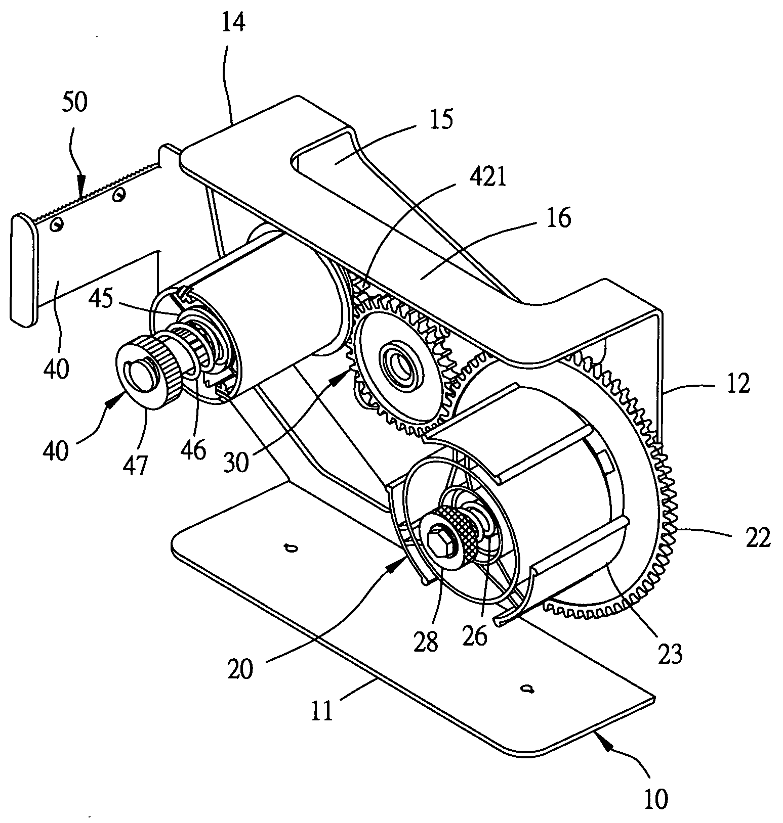
[0016] A first preferred embodiment of a separable paper stripping device in the present invention, as shown in FIGS. 1 to 6, includes a base 10, a paper-roll holder 20, an idle gear 30, a separable-paper holder 40 and a cutting member 50 combined together.

[0017] The base 10 is formed with a bottom plate 11 having its opposite sides respectively bored with an insert hole 111 at a proper location for a bolt 112 to be inserted therein to fix the bottom plate 11 on a flat stand. The bottom plate 11 has one side extending upward vertically and forming a first wall plate 12 that has its left side extending transversely to form a second wall plate 13 and has its upper end bent properly to form a third wall plate 14. A hole 15 is bored in the bent portion between the first and the third wall plates 12 and 14, letting the third wall plate 14 positioned at the outer side of the hole 15 serve as a grip 16.

[0018] The paper-roll holder 20, as shown in FIG. 4, is provided with a shaft 21 havin...


PUM

PropertyMeasurementUnit
Circumferenceaaaaaaaaaa

Abstract

A separable paper-stripping device includes a base formed with a first and a second wall plate. The first wall plate is assembled thereon with a paper-roll holder, an idle gear and a separable-paper holder, and the second wall plate is secured thereon with a cutting member. The paper-roll holder is provided with a first gear able to actuate the second gear of the separable-paper holder to rotate through the idle gear. After a separable-paper roll is fitted on the paper-roll holder and the end of separable paper stripped from the separable-paper roll is fixed in the separable-paper holder, the sticking paper and the separable paper can be continuously separated from each other by pulling forward the end of the stripped sticking paper, and simultaneously the stripped separable paper can be rolled up by the separable-paper holder.

Description

BACKGROUND OF THE INVENTION [0001] 1. Field of the Invention [0002] This invention relates to a separable paper stripping device, particularly to one able to separate sticking paper from separable paper easily and quickly. [0003] 2. Description of the Prior Art [0004] Generally, a separable-paper roll is composed of sticking paper and separable paper that is pasted on one side or on both sides of the sticking paper. The separable paper and the sticking paper of a separable-paper roll have to be manually separated from each other first whenever the sticking paper is to be used for pasting, resulting in inconvenience in use. Therefore, various separable-paper stripping devices have been designed for facilitating stripping separable paper. [0005] However, a conventional separable paper-stripping device is complicated in structure and it is provided with no device for controlling the tightness in rotation of a separable-paper roll for rolling up separable paper. Thus, the separable-pape...

Claims


Application Information

Patent Timeline
IPC IPC(8): B29C63/00B65H16/04
CPCB65H35/0026Y10T156/1168Y10T156/195B65H37/002
Inventor YU CHEN, HSIU-MAN
Owner YU CHEN HSIU MAN
Learn More