Levitation of objects using magnetic force

a technology of magnetic force and objects, applied in the field of levitation objects, can solve problems such as stop working, and achieve the effect of enhancing the appeal of objects and ensuring the stability of objects

Inactive Publication Date: 2006-09-28
ELLIHAY CORP
View PDF50 Cites 155 Cited by
  • Summary
  • Abstract
  • Description
  • Claims
  • Application Information

AI Technical Summary

Benefits of technology

[0007] One preferred embodiment is a method to secure an object in a manner to give the appearance of levitation of either one end of the object or the object as a whole. One end of the object is permanently or temporarily fixed by mechanical or magnetic means while the other end is free to levitate or “float” in midair. By fixing one end, the overall stability of ...

Problems solved by technology

Wear and tear or overloading of these comp...

Method used


Image

  • Levitation of objects using magnetic force
  • Levitation of objects using magnetic force
  • Levitation of objects using magnetic force

Examples


Embodiment Construction

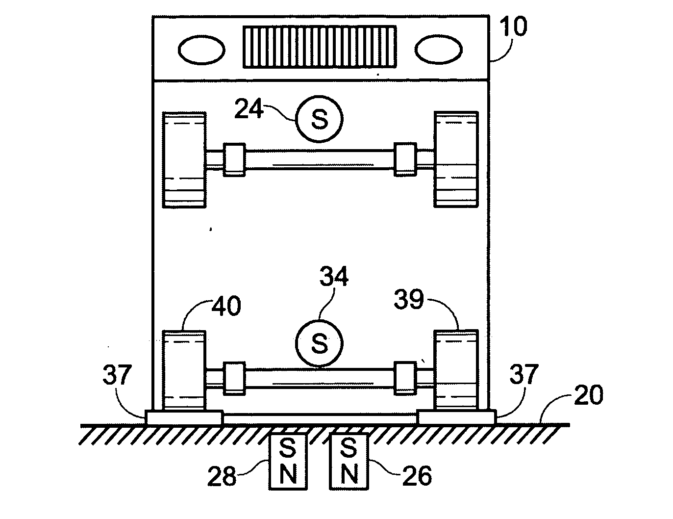
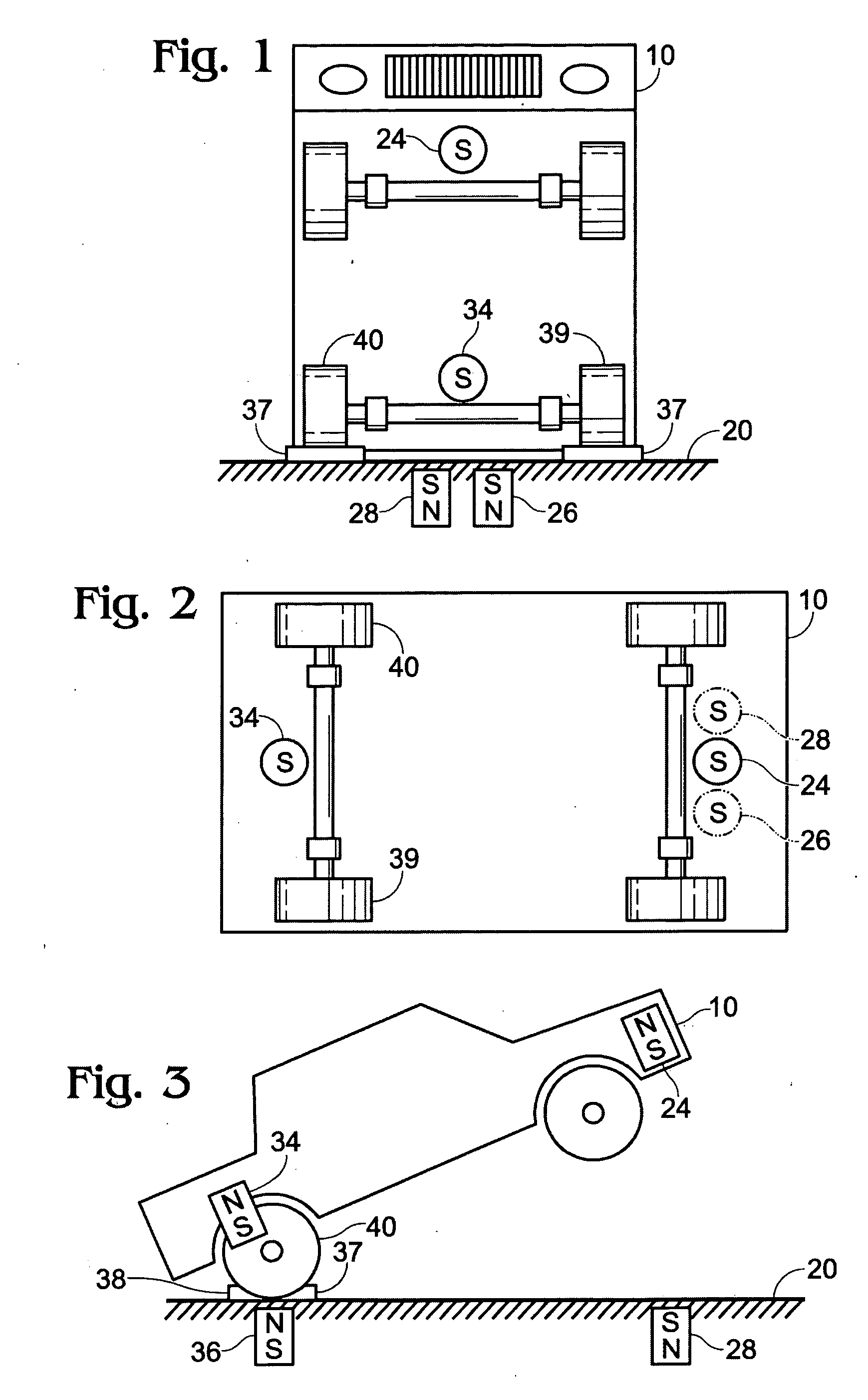
[0027] With reference to FIGS. 1-11 a first, preferred embodiment of a method and assembly for providing full and partial levitation of an object without mechanically generated movement is described next.

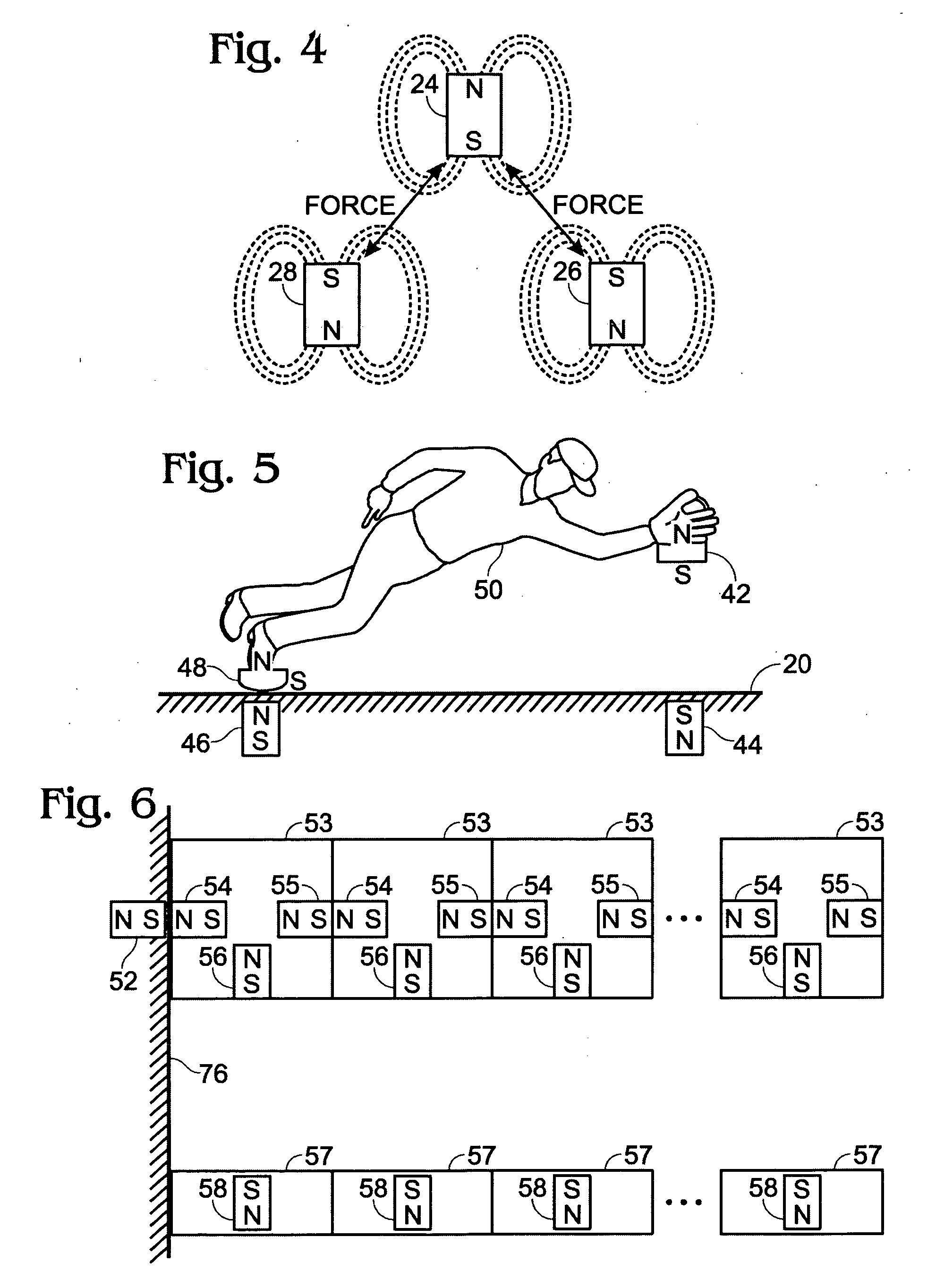
[0028]FIGS. 1-3 present a vehicle 10 with the front end levitated. Magnet 24 is located inside the body or attached on the surface of the vehicle 10. Magnets 28 and 26 are located on or below the surface of base 20. The south-pole end of magnet 24 is oriented downward toward magnets 28 and 26, which have their south-pole ends pointing upward. This arrangement provides a repulsive force between magnet 24 in the vehicle and the two magnets 28 and 26 in the base. Magnets 24, 28 and 26, if chosen properly create a magnetic repulsive force that is more powerful than the force of gravity acting on the mass of the vehicle.

[0029] A channel is created by wedges 37, 38 on the surface of the base 20. The wedges serve to locate one pair of the vehicle's wheels 40 and 39 and magnet 34 directly...


PUM


Abstract

The invention disclosed is a method of levitating one or both ends of an object permanently or temporarily, or altering the distance between two objects or the momentum of an object by manipulating the direction of the magnetic field of a permanent or electromagnet.

Description

TECHNICAL FIELD [0001] This application relates to levitating objects by manipulating the orientation of the magnetic field of a permanent magnet or electromagnet. BACKGROUND [0002] Magnets contain properties commonly known for centuries. Magnets contain two poles, one north (N) and one south (S). Opposite poles attract, and like poles repel. [0003] Magnetic fields have long been used in various applications. Magnetic attraction forces can provide utility by temporarily securing items to a ferromagnetic surface or by orienting items in ways to increase their functionality. Many products can utilize the repulsive force of two or more magnets to create novel designs for consumer products. [0004] Mechanical gears and motors are often used to move objects. Wear and tear or overloading of these components, however, can cause them to stop working. A static or changing magnetic field can be used as a driving force in place of, or in conjunction with, mechanical gears and motors, thereby ex...

Claims


Application Information

Patent Timeline
IPC IPC(8): H01F7/02
CPCH01F7/0236H01F7/206H02N15/00
Inventor ELLIOTT, TODD S.HAYHURST, WILLIAM F.
Owner ELLIHAY CORP
Why Eureka
Try Eureka