Lighting device for adjusting a light colour separately within severla zones

a technology of lighting devices and severla zones, applied in the direction of optical radiation measurement, instruments, spectrometry/spectrophotometry/monochromators, etc., can solve the problems of inconvenient use of multiple lighting devices, time required for operators to direct the light beams of all lighting devices towards, and the total cost of multiple lighting devices which are necessary to suit any content of the shop window

Inactive Publication Date: 2016-05-26
SIGNIFY HLDG BV
View PDF2 Cites 17 Cited by
  • Summary
  • Abstract
  • Description
  • Claims
  • Application Information

AI Technical Summary

Benefits of technology

[0017]For improved colours of the light beams which are directed onto separate elements, and increasing the appeal to an observer, the spectral source feature of at least one of the light systems may correspond to white light, or the spectral detection range of at least one of the light systems may correspond to white light, or both may be combined.
[0018]For improved colours of the light beams which are directed onto separate elements, and increasing the appeal to an observer, a maximum number of light systems with different wavelengths can be used so as to provide a richer spectral resolution and improve the lighting device performances, or the spectral detection range of the light systems may correspond to a maximum of light systems of different wavelengths.
[0021]In preferred embodiments of the invention, each light system may be based on a LED which is connected to a power source so as to operate either as light detector or as light source. Such embodiments are low-cost, and provide exact matching between light detection directions which are involved in step / 1 / and light production directions involved in step / 3 / . Thus, the light beams with different colours can match the outlines of the elements contained in the scene even more accurately, with beam overlaps on the neighbouring elements which are more reduced.
[0022]In such LED-based embodiments, the processing unit may be adapted also for controlling the LEDs and the scanning system during step / 3 / . Then, it may be further adapted for implementing intensity time-modulation with at least one of the light systems, simultaneous lighting of different ones of the zones by at least two of the light systems, or a combination of both such time-modulation and simultaneous lighting, when directing light within the zones in accordance with the target intensities. In this way, more efficient lighting can be obtained, together with better colour setting and reduced energy consumption.
[0023]Independently or in combination with the preceding advantageous and / or preferred embodiments, the scanning system may comprise a digital mirror device. Such scanning system is reduced in dimensions, commercially available, and its implementation is well-known. Combined implementations using both LEDs and digital mirror devices are even more advantageous, because they allow rapid scanning of the output field with instant light colour possibly modulated at scanning rate. Scanning rate values up to 100 Hz (hertz) or more can be obtained in this way, producing very good visual rendering while minimizing flickering effects.

Problems solved by technology

However each light device produces a light beam which does not match the cloth outline as existing in the shop window, so that a customer is aware of the lighting effect.
Another drawback is the total cost of the multiple lighting devices which are necessary to suit any content of the shop window and its arrangement in space.
Still another drawback is the time necessary for an operator to direct the light beams of all the lighting devices towards the right articles exhibited.
But there are also applications in which using multiple lighting devices is not appropriate, because the elements to be illuminated with different colours are close to one another.

Method used


Image

  • Lighting device for adjusting a light colour separately within severla zones
  • Lighting device for adjusting a light colour separately within severla zones
  • Lighting device for adjusting a light colour separately within severla zones

Examples


Embodiment Construction

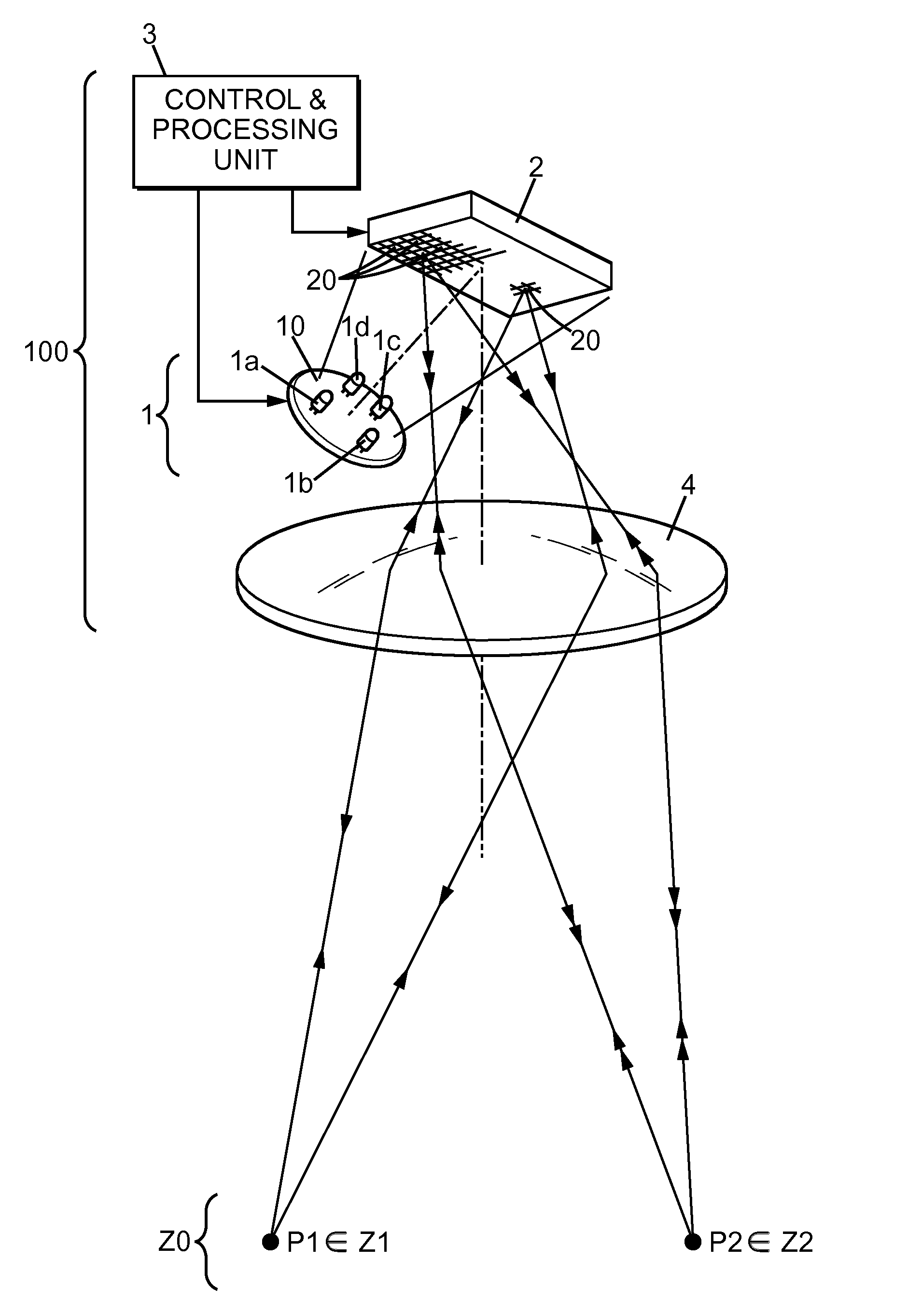
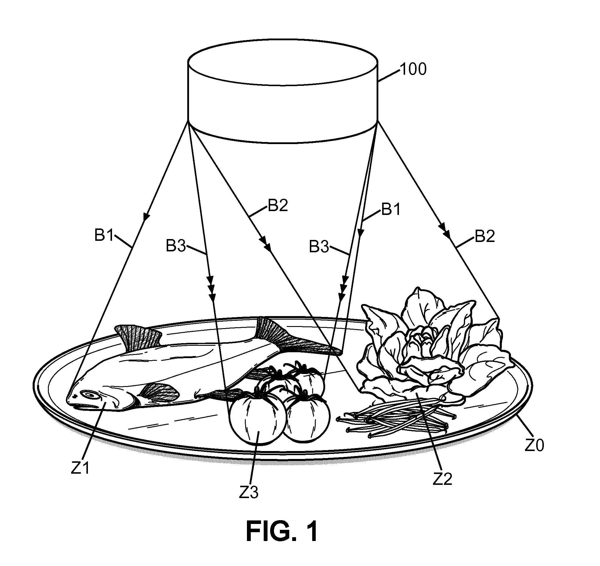
[0031]In FIG. 1, reference label Z0 denotes a composite food plate which contains several food elements of different colours: a fish portion Z1, green vegetables Z2 and tomatoes Z3. Such plate is to be exhibited in a restaurant presentation, for example. It is to be illuminated using the lighting device 100 which is arranged above the plate Z0, at about 40 cm from this latter. For appealing to the restaurant customers, the fish portion Z1 is to be illuminated with a white or bluish light beam denoted B1 and marked with single arrows, the vegetables are to be illuminated with a greenish light beam denoted B2 and marked with duplicated arrows, and the tomatoes with a reddish light beam B3 with triplicate arrows. But such appeal-enhancing effect would be spoilt if the greenish light beam B2 or the reddish light beam B3 also impinges onto the fish portion Z1, possibly giving to the customers the disastrous impression that the fish portion is somewhat rotten. Therefore, the beams B1 to B...


PUM


Abstract

A lighting device (100) is suitable for adjusting a light colour with respect to elements contained within an output field, separately for each element. The lighting device comprises at least two light systems (1a-1d) each adapted for operating as a light detector and also as a light source, a scanning system (2) suitable for scanning the output field, and a processing unit (3). Such lighting device is especially adapted for exhibiting articles with producing enhanced appeal to an observer. To this purpose, light which is directed towards each element may be enhanced in saturation and brightness as compared to initial light reflected by the element, while hue may be substantially maintained.

Description

[0001]The invention relates to a lighting device which is capable of varying a light colour between different zones within a lighting field.BACKGROUND OF THE INVENTION[0002]There are applications for lighting devices which require directing light with varying spectral features towards separate zones within a total field to be illuminated. Indeed, elements or manufactured articles with different respective colours may be illuminated each with light of suitable colour, for making this article more appealing to an observer. Such requirement exists in particular for lighting devices which are implemented in shop windows, for example clothing windows or food display shelves. For the example of exhibiting a food plate with green vegetables and meat, colours can be enhanced when lighting the vegetables with greenish light and the meat with reddish light. Then, the composite food plate can be made more appealing to a customer. But the effect obtained will be mitigated or even spoilt if ligh...

Claims


Application Information

Patent Timeline
Patent Type & Authority Applications(United States)
IPC IPC(8): H05B33/08G02B26/08G02B26/10G01J3/50G01J1/44H05B44/00
CPCH05B33/0869G01J3/501G02B26/0833G02B26/101G01J1/44A47F11/10G01J3/10G02B26/123G02B26/127H05B45/20H05B45/22
Inventor MONTAGNE, LOUIS-XAVIER MARIE
Owner SIGNIFY HLDG BV
Why Eureka
Try Eureka