
Display device and display method

a display device and display method technology, applied in the field of display devices and display methods, can solve the problems of nonlinear change in chromaticity, expression (3) cannot deal with the case in which another modulator is present, and the two-modulation type display device cannot deal with the usual one-modulation type color management, etc., to achieve precise color reproduction and simple constitution

Inactive Publication Date: 2006-09-28
SEIKO EPSON CORP
View PDF8 Cites 15 Cited by
  • Summary
  • Abstract
  • Description
  • Claims
  • Application Information

AI Technical Summary

Benefits of technology

The invention provides a display device and method that can accurately reproduce colors using a two-modulation type color management system. This is achieved by using a three-dimensional look up table created based on a measurement result of the color control signal corresponding to a predetermined luminance value. The use of the three-dimensional look up table simplifies the processing of color conversion and reduces costs. Additionally, the signal processing unit can determine the luminance control signal and color control signal independently, increasing flexibility and image quality. The invention also includes a method for controlling the display device using a three-dimensional look up table. Overall, the invention improves color reproduction and image quality while reducing costs.

Problems solved by technology

Therefore, the two-modulation type display device cannot deal with the usual one-modulation type color management.
However, the expression (3) cannot deal with the case in which another modulator, for example, a liquid crystal panel changes in chromaticity in accordance with the modulation.
Further, in a case that modulation is performed using a liquid crystal panel in place of the modulation light source, the change in chromaticity is nonlinear.
In the above related arts, in a case that a modulator such as the liquid crystal panel, which has characteristic that chromaticity changes nonlinearly in relation to modulation is used in the two-modulation type display device, there is a problem that it is difficult to obtain precise color reproducibility.
Therefore, in case that the number of the elements to be processed is simply increased, there can be a problem that the number of processing steps increases, or a circuit scale increases when the precise color reproducibility is realized by hardware such as LSI (Large Scale Integration).

Method used


Image

  • Display device and display method
  • Display device and display method
  • Display device and display method

Examples


Embodiment Construction

[0024] One embodiment of the invention will be described below with reference to drawings. A display device in the embodiment is a two-modulation type display device which includes a color modulator and a luminance modulator separately. In the display device, a signal processing part for generating a control signal of each modulator or performing color management can be composed of a microprocessor system which incorporates hardware such as LSI and a software program to operate. However, a part or all of the signal processing part may be also composed of a general-purpose computer and a program in which processing of the invention is written.

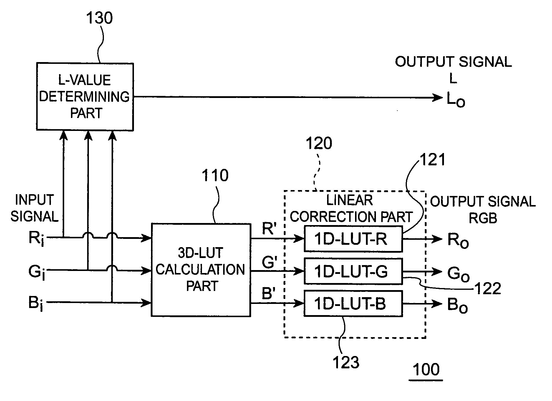
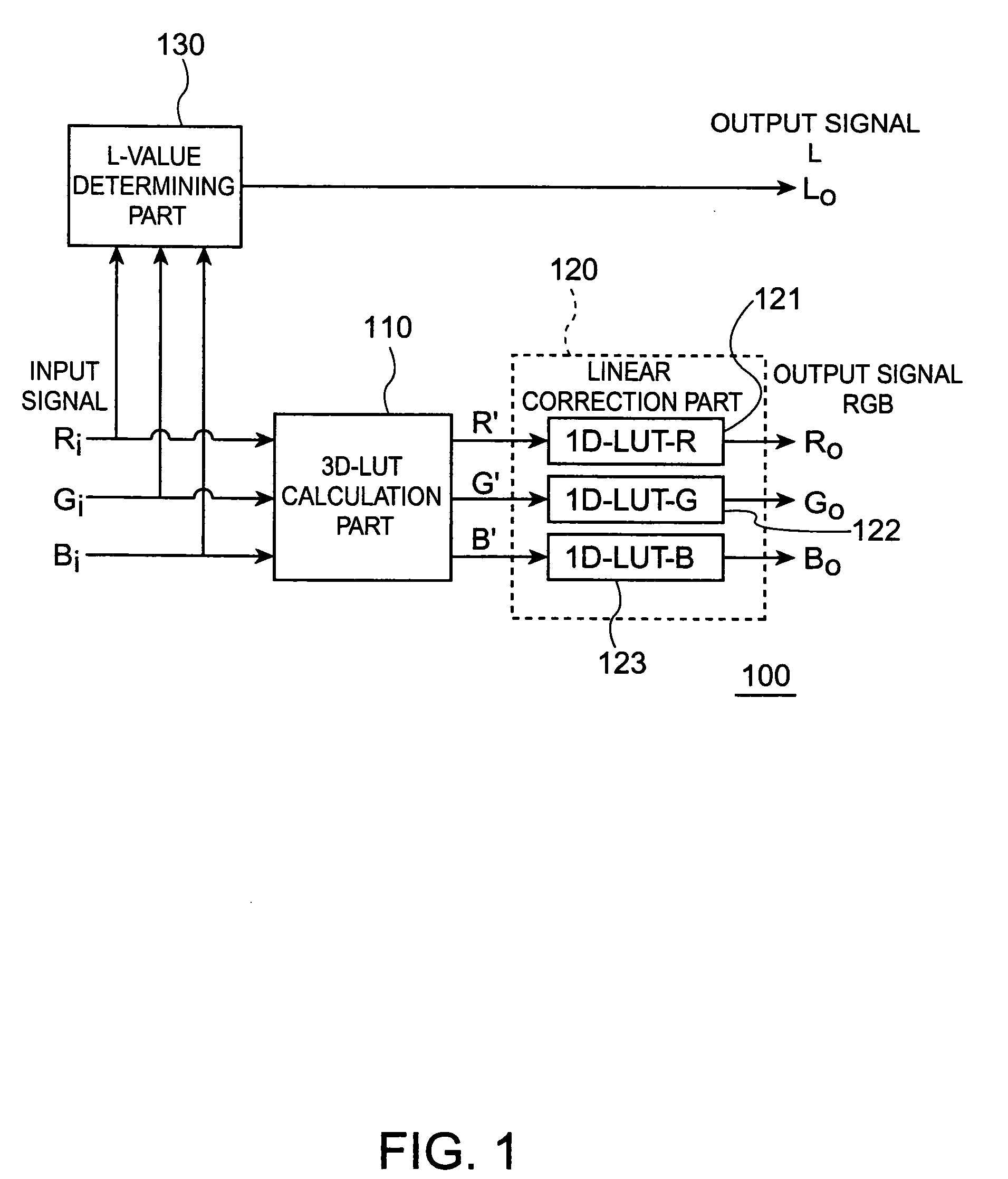
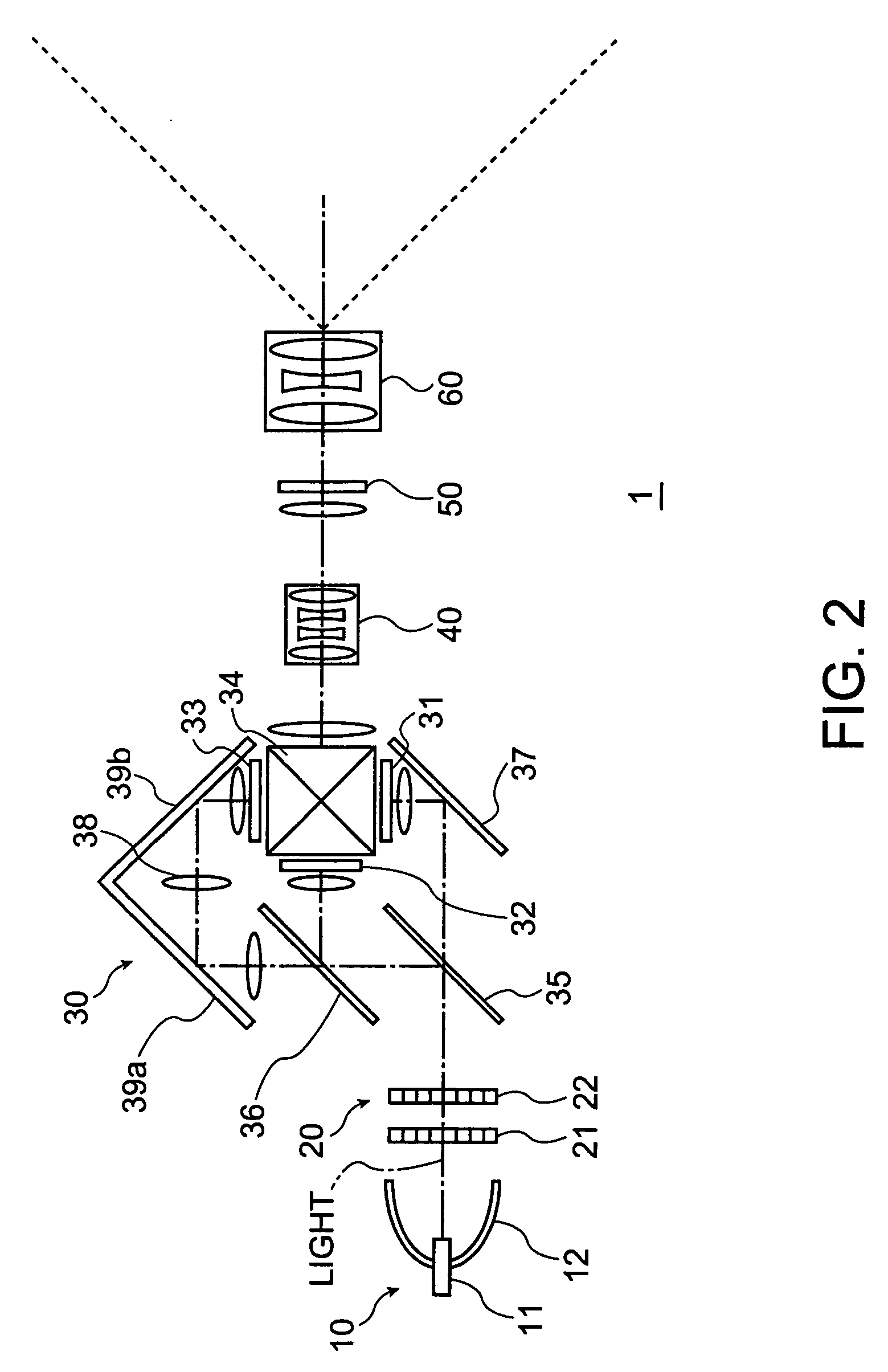
[0025]FIG. 1 is a block diagram showing a constitutional example of a signal processing part 100 in one embodiment of a display device according to the invention. FIG. 2 is a block diagram of a HDR display 1 as a constitutional example of the display device in this embodiment.

[0026] As shown in FIG. 2, regarding the constitution of each modula...


PUM


Abstract

A display device includes a luminance modulator and a color modulator which are formed of separate modulators. Herein, when, in order to reproduce an input signal, a luminance control signal of the luminance modulator and a color control signal of the color modulator are determined by the input signal, a three-dimensional look up table which is created on the basis of a measurement result relating to the color control signal corresponding to the predetermined luminance value is used, whereby the color control signal of the color modulator is determined by the input signal.

Description

BACKGROUND [0001] 1. Technical Field [0002] The present invention relates to a display device suited to use in a HDR (High Dynamic Range) display which uses a two-modulation system, PTV (Projection TV), DTV (Digital TV), FPD (Flat Panel Display), and the like. [0003] 2. Related Art [0004] In case of a two-modulation type display device, to the usual one-modulation system, another modulation system is connected optically in series. Therefore, the two-modulation type display device cannot deal with the usual one-modulation type color management. Therefore, a proposal as described below has been made. [0005] The related art disclosed in Japanese Patent No. 3,523,170, relates to the two-modulation type, in which a modulation light source is used as one modulation system. Modulation of the light source is performed by combination of steady-state illumination by a cold cathode tube and modulated illumination by a white LED (Light Emitting Diode). Therefore, due to difference in emission s...

Claims


Application Information

Patent Timeline
Patent Type & Authority Applications(United States)
IPC IPC(8): G09G5/02
CPCG09G3/3406G09G2320/0646G09G2360/16H04N9/3182
Inventor NITTANAKAMURA, JUNICHIUCHIYAMA, SHOICHIASAHI, TSUNEMORI
Owner SEIKO EPSON CORP
Learn More