Laser scanning and power control in a rapid prototyping system

a technology of rapid prototyping and laser scanning, applied in the field of rapid prototyping systems, can solve the problems of difficult design of a practical encoder circuit, high-speed, high-resolution applications, and the voltage versus angle of the monotonic respons

Active Publication Date: 2006-09-28
3D SYST INC
View PDF6 Cites 65 Cited by
  • Summary
  • Abstract
  • Description
  • Claims
  • Application Information

AI Technical Summary

Benefits of technology

The patent describes how multiple sequences can be scanned without sudden changes in direction or speed. This results in smoother movements during data transfer and analysis.

Problems solved by technology

The technical problem addressed in this patent text relates to improving the precision and accuracy of laser scanning in rapid prototyping devices. More specifically, the challenge comes from the non-uniform distribution of light caused by the dynamics of the laser's optical elements, including the scanning mirrors and the laser itself. To address these issues, the patent proposes a method for controlling both the laser power and the scanning speed simultaneously to ensure accurate exposure patterns and optimal exposure settings during the build process.

Method used


Image

  • Laser scanning and power control in a rapid prototyping system
  • Laser scanning and power control in a rapid prototyping system
  • Laser scanning and power control in a rapid prototyping system

Examples


Embodiment Construction

[0048] The present inventions now will be described more fully hereinafter with reference to the accompanying drawings in which some, but not all, embodiments of the inventions are shown. Indeed, these inventions may be embodied in many different forms and should not be construed as limited to the embodiments set forth herein; rather these embodiments are provided so that this disclosure will satisfy applicable legal requirements. Like numbers refer to like elements throughout.

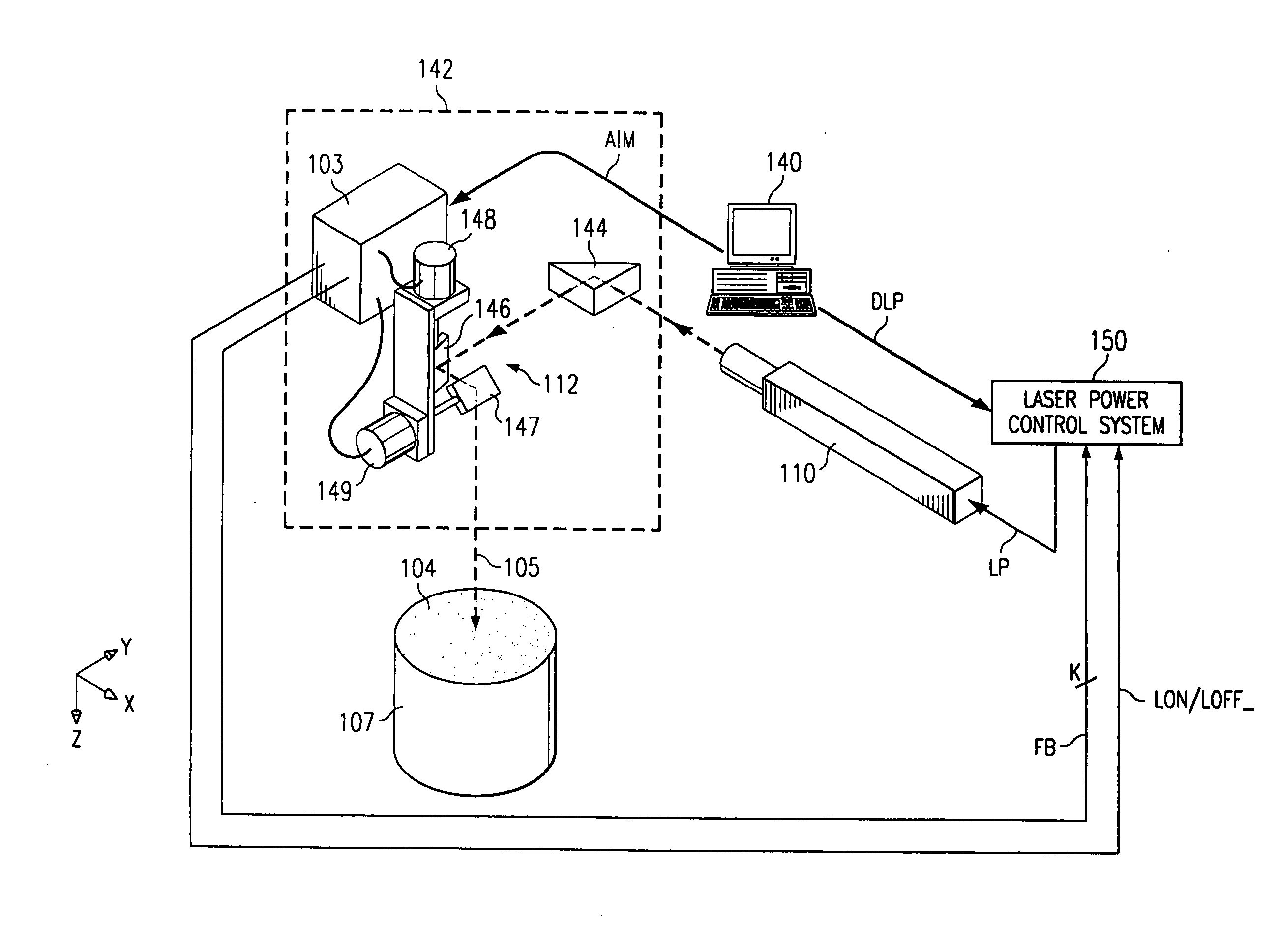
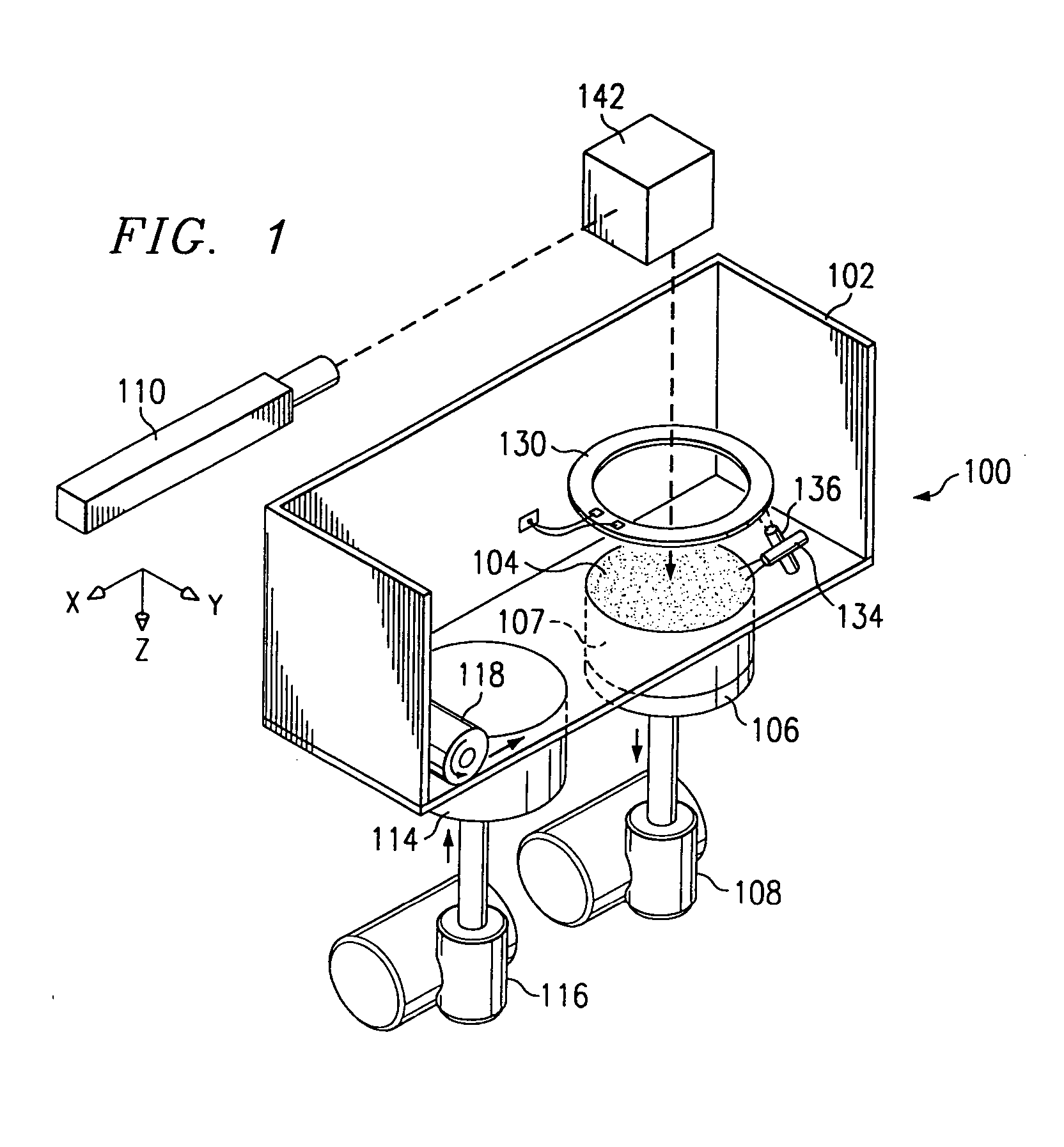
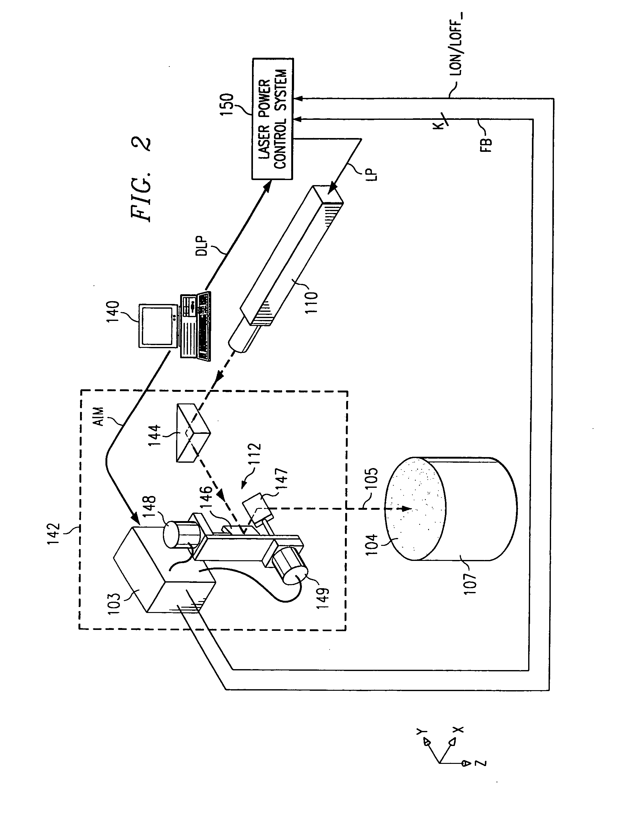
[0049] As will become apparent from the following description, the present invention may be utilized in connection with laser control systems generally, regardless of the particular application of the laser to be controlled. However, it has been observed that the present invention is particularly beneficial when applied to rapid prototyping systems that utilize lasers in the fabrication of articles from computer-aided-design (CAD) or computer-aided-manufacturing (CAM) databases. Accordingly, the following des...


PUM

PropertyMeasurementUnit
Timeaaaaaaaaaa
Timeaaaaaaaaaa
Timeaaaaaaaaaa

Abstract

A laser scanning system in a rapid-protyping system is controlled during vector scanning by providing a commanded-position signal to each of first and second rotary motive devices to rotate respective mirrors of the scanning system, each mirror undergoing acceleration at the beginning of the vector, wherein the commanded-position signals are calculated based on physical mathematical modeling of the acceleration of the mirrors taking into account effects of inertia of the scanning system, and wherein actual positions of the mirrors are measured with fast-response devices and digital feedback control of the mirror positions is employed at a periodic rate sufficiently small to maintain a following error of the laser spot less than about 200 μs at all times. A laser power control method employs a fast-response power meter for measuring laser power.

Description


Claims


Application Information

Patent Timeline
Owner 3D SYST INC
Why Eureka
Try Eureka