Eureka AIR delivers breakthrough ideas for toughest innovation challenges, trusted by R&D personnel around the world.

Instrument for the surgical removal of a defective heart valve

a heart valve and surgical technology, applied in the field of instruments for the surgical removal of defective heart valves, can solve the problems of additional problems, substantial difficulty in subsequent surgical insertion of a new heart valve,

Active Publication Date: 2008-08-07
ENDOSMART GES FUR INNOVATIVE MEDIZINTECHN
View PDF11 Cites 53 Cited by
  • Summary
  • Abstract
  • Description
  • Claims
  • Application Information

AI Technical Summary

Benefits of technology

[0014]The object of the present invention consists of further developing the above-described instrument according to the preamble to the claim so that on the one hand, it maintains the surgical advantages that result from the fact that the cutting tools can be collapsed and expanded radially and that a contact protective sheath is used, so that on the other hand, however, it will be assured so that the above-named disadvantages are avoided, i.e., that no problems occur during surgery when the contact protective sheath is moved onto the two body members again, so that disturbances in the functionality of the instrument do not occur due to undesired “chipping” of the defective heart valve, and that finally, the production of a true-to-size circular cut is also assured when the defective heart valve is removed, and thus the subsequent surgical insertion and attachment of a new heart valve is made possible without problem.SUMMARY OF THE INVENTION
[0016]During use of the two body members (during use, the cutting ring of the respective body member is fully expanded in the radial direction and adjusted precisely to a circle), the inventive concept utilizes the dimensional stability of a flat material strip, which is pre-shaped by manufacturing techniques in edge-wise format to a semicircular arc. This pre-shaping is a deformation or strain reinforced in the material structure and therefore precisely dimensioned. The dimensional stability is supported by attaching the two ends of the respective semicircular arc to the above-named hinge axes, which in turn are each attached by the head end of a fish joint and are attached to the elongated member of the instrument in the axial direction. In addition, the respective center of the semicircular arc is also axially attached to the elongated member of the instrument by another fish joint, so that the axial position and the necessary precision of the cutting ring diameter of the two body members is also assured by means of these fish joints.
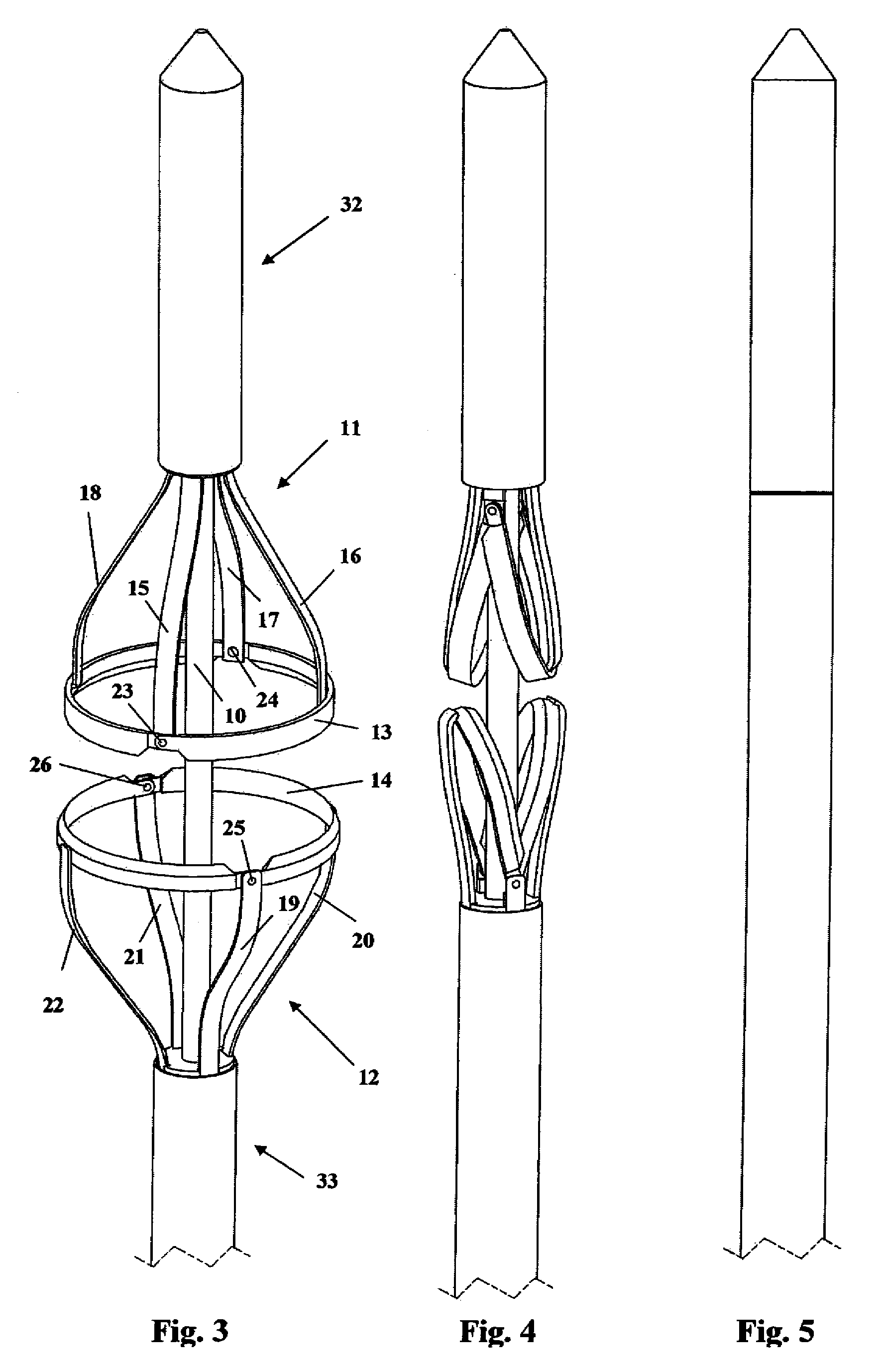
[0020]The above-named bearing designs of the respective foot ends of the fish joints define a functional course when the cutting ring halves are collapsed, which is characterized in that the fish joints which attach the respective center of the semicircular arcs of the cutting ring halves remain in their axial position, while on the other hand, the fish joints whose head ends are joined with the hinge axes of the cutting ring can be moved and stopped axially, so that they bring about a folding in of the cutting ring around its hinge axes and simultaneously cause the cutting ring halves to deform to a half-shape of a constricted oval or similar shape around their centers held in the respective axial position.
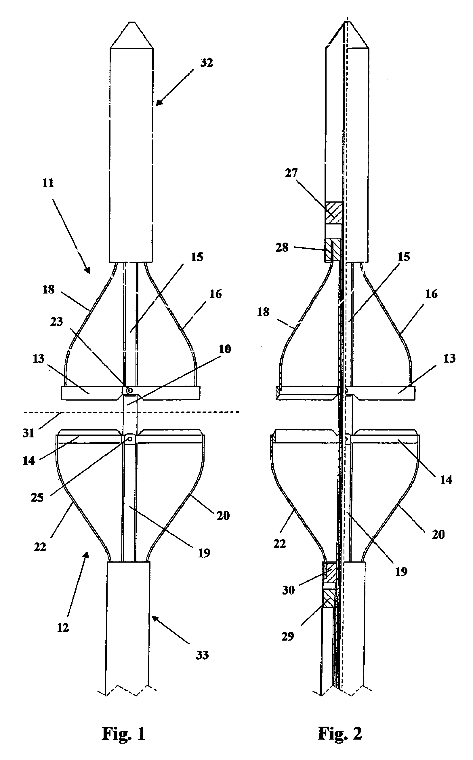
[0024]Both in the expanded state of the cutting ring as well as in the collapsed state of the cutting ring halves, the fish joints configure meridians of a funnel-shaped body, which can be ideally utilized to push a contact protection sheath that fits closely to the elongated member relative to its diameter onto the cutting elements of the folded-in cutting ring halves. The smooth transitions of this funnel shape and the elastic yielding of the fish joints in the radial direction assure that a contact protection sheath can be moved onto and / or again pulled off the folded-in instrument cutting elements at any time (and even repeatedly during surgery).
[0027]It can additionally be provided that the body members with their cutting rings can rotate relative to one another in such a way that the defective heart valve will be cut out by a rotating-punching process.

Problems solved by technology

Problems may occur when the contact protective sheath is again moved onto the two body members, since despite identical manual manipulations, spirally wound cutting elements may have different spiral configurations and thus different outer diameters.
Another disruption in the functionality of the above-named instruments results from the fact that the spirally wound cutting elements do not produce a geometrically circular cut, whereupon the subsequent surgical insertion of a new heart valve is made considerably difficult, especially since currently all mechanically produced heart valve prostheses have a circular base for attachment.
It is also a considerable disadvantage that the spirally wound cutting elements of the known instruments of this type do not cut out a defective heart valve as a one-part valve piece, but the valve piece is primarily “chipped off” between its spiral cutters.
In this way, additional problems arise and it is necessary to arrange catching devices and / or filter screens in order to prevent the “chipped off” tissue fragments from entering the bloodstream of the patient.

Method used


Image

  • Instrument for the surgical removal of a defective heart valve
  • Instrument for the surgical removal of a defective heart valve
  • Instrument for the surgical removal of a defective heart valve

Examples


Embodiment Construction

[0031]The basic construction of an instrument according to the invention is best seen from FIG. 3 in combination with FIGS. 1 and 2.

[0032]The central elongated member 10 can be recognized, which continues downward in the representations to an instrument handle, which is not shown in the figures, since it can be of usual structure and configuration. In and on such handle, various actuators and stopping mechanisms are present, by means of which the functional parts of the instrument, such as will be named below, can be individually controlled (adjusted) and / or stopped. This is usually performed by means of control rods running parallel to the elongated member and / or coaxial control sleeves guided into one another.

[0033]Two body members 11 and 12 that are formed in mirror image to one another are present coaxially around elongated member 10, each body member having a cutting ring 13 or 14, each with their four fish joints 15 to 18 or 19 to 22 for each ring, the fish joints each being m...


PUM


Abstract

An instrument for the surgical removal of a defective heart valve. The instrument has elements that can be collapsed, in which the instrument cutting elements are collapsed when the instrument is introduced into the surgical field and are covered by means of contact protective sheaths. The instrument cutting elements are formed as cutting ring halves that can fold in around a hinge axis, these cutting ring halves being elastically deformable during the folding-in process, whereby their deformation is achieved by fish joints that also serve to aid in mutually moving the contact protective sheaths onto each of two body members.

Description

TECHNICAL FIELD[0001]The invention relates to an instrument for the surgical removal of a defective heart valve.BACKGROUND OF THE INVENTION[0002]Such instruments are primarily used for a single task, i.e., only for the removal of the defective heart valve, but instruments of this type are also known that include additional functions, which make it possible, for example, to insert a new heart valve with the same instrument and in the same surgical procedure after the removal of the defective heart valve (see DE 600 17 189 T2, FIG. 1 therein, reference number 10 with the description belonging thereto).[0003]It is also known to provide instruments of this type with catching devices and / or with filter screens that can be clamped on, for example, in order to prevent fragments of tissue that are freed during the surgical removal of a defective heart valve (which is also usually calcified) and / or material deposits from entering the bloodstream of the patient (see the above-named DE 600 17 ...

Claims


Application Information

Patent Timeline
Patent Type & Authority Applications(United States)
IPC IPC(8): A61B17/32
CPCA61B17/320016A61B17/32053A61F2/24A61B2017/00243A61B17/320725
Inventor FISCHER, HARALDHAUCK, FLORIAN
Owner ENDOSMART GES FUR INNOVATIVE MEDIZINTECHN
Why Eureka
Eureka Blog
Learn More