Attachment device for building materials

Inactive Publication Date: 2006-09-28
SHARKOZY MARK CHRISTOPER
13 Cites 6 Cited by

AI-Extracted Technical Summary

Problems solved by technology

The first factor is that the cost of wood building materials has increased dramatically due to their decreasing availability.
Wood building materials such as, for example, wood wall studs have become less available and, accordingly, more expensive.
Additionally, in many instances, this decreasing availability has lead to a corresponding decrease in overall quality of such wood building materials.
One drawback of constructing walls from cinder blocks is that subsequent construction of interior walls using conventional approaches is time-consuming and prone to damage the underlying cinder blocks.
The drawback to this approach is that the furring strips are attached to a cinder block wall by driving nails through the furring strips and into the cinder block wall, by gluing...

Benefits of technology

[0007] Embodiments of the present invention enable elongated members and other articles to be attached to masonry block structures such as walls constructed from masonry blocks. More specifically, embodiments of attachment devices in accordance with the present invention allow elongated members such as, for example, furring strips, studs, cables and pipes to be attached to walls constructed from, for example, masonry blocks, foam b...

Abstract

An adjustable attachment device for building materials comprises a first U-shaped engagement structure and a second U-shaped engagement structure that is attached to a leg of the first U-shaped engagement structure. The second U-shaped engagement structure is at least one of pivotably attached to the leg of the first U-shaped engagement structure and translatably attached to the leg of the first U-shaped engagement structure. A central portion of the second U-shaped engagement structure is attached to the leg of the first U-shaped engagement structure. The first U-shaped engagement structure is adjustable between a first position whereby a respective channel of the first U-shaped engagement structure and a respective channel of the second U-shaped engagement structure extends generally parallel with a first reference axis and a second position whereby the respective channel of the second U-shaped engagement structure extends generally perpendicular to the first reference axis.

Application Domain

CeilingsScaffold connections +3

Technology Topic

Building materialEngineering

Image

  • Attachment device for building materials
  • Attachment device for building materials
  • Attachment device for building materials

Examples

  • Experimental program(1)

Example

DETAILED DESCRIPTION OF THE DRAWINGS
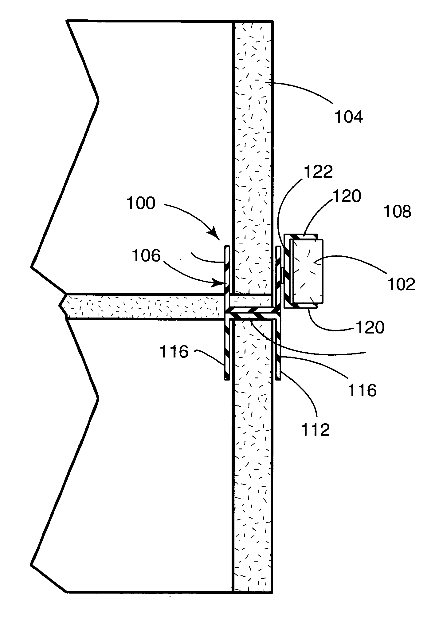
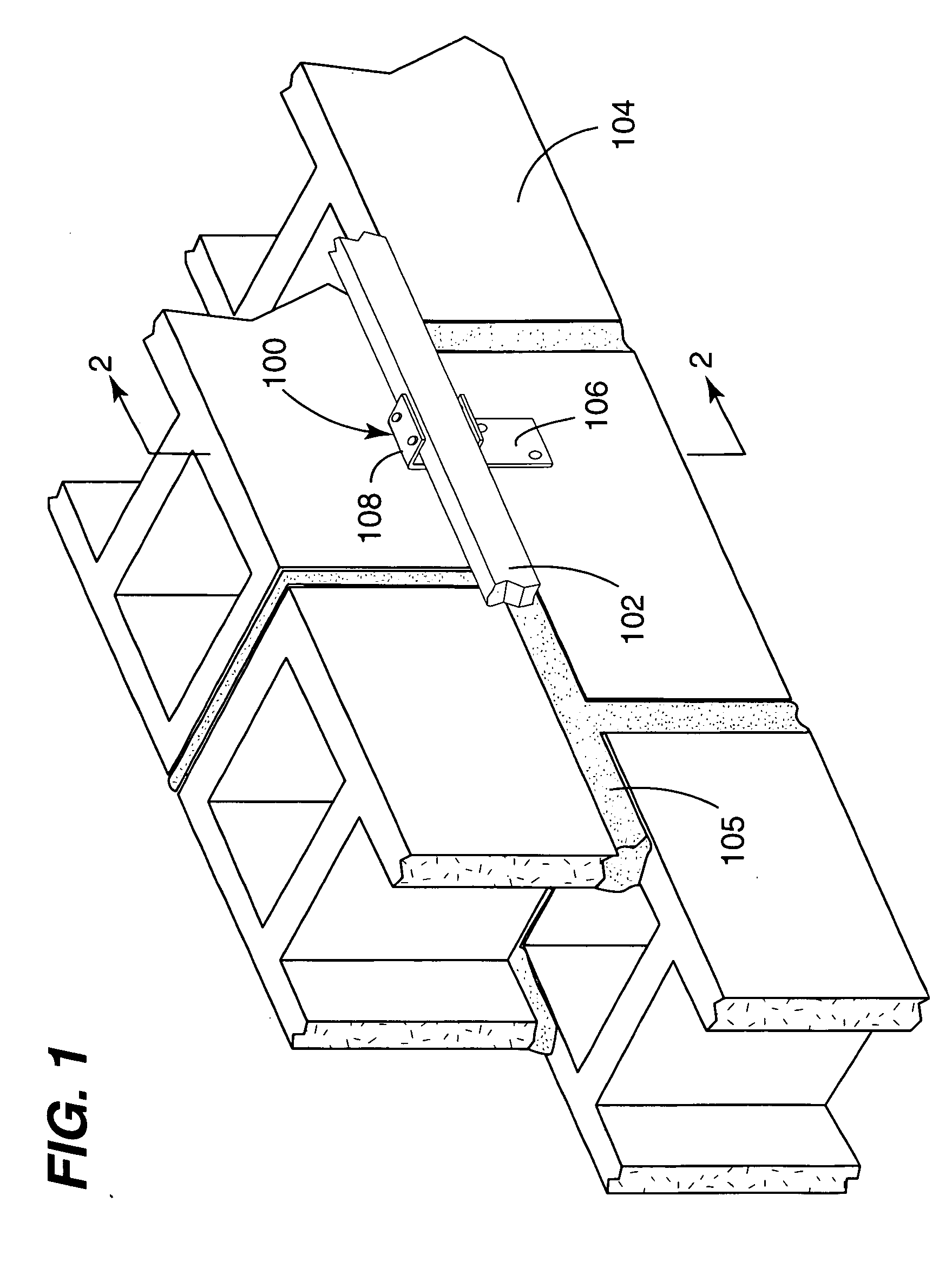
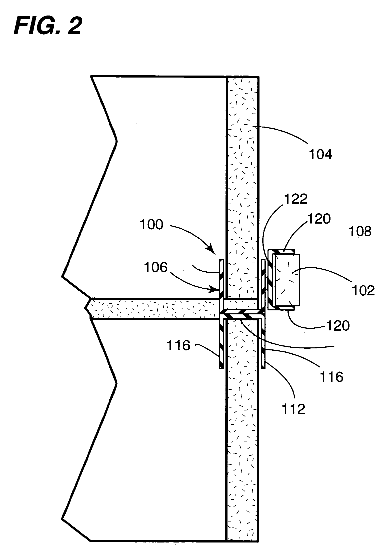
[0028]FIGS. 1-5 depict an embodiment of an attachment device for building materials in accordance with the present invention, referred to generally as the attachment device 100. As depicted in FIGS. 1 and 2, the attachment device 100 is suitably configured for attaching an elongated structural member 102 (e.g., a furring strip or stud) to a wall 104 constructed from, for example, masonry blocks (e.g., cinder blocks). During construction of the wall 104, the attachment device 100 and a plurality of other identical attachment devices are installed such that mortar 105 secures the attachment devices in place. Fasteners such as, for example, nails or screws are used to secure the elongated structural member 102 to the attachment member 100. Thus, a plurality of attachment devices in accordance with the present invention serves to secure elongated structural members (e.g., the elongated structural member 102) to the wall 104.
[0029] The attachment device 100 has a wall engagement structure 106 and an elongated member engagement structure 108. The wall engagement structure 106 is suitably configured for engaging the wall 104, which is constructed from masonry blocks. The elongated member engagement structure 108 is suitably configured for engaging the elongated member 102.
[0030] Referring to FIGS. 3-5, the wall engagement structure 106 includes pair of U-shaped engagement structures (110, 112). A plurality of fasteners 114 such as, for example, rivets secure the pair of U-shaped engagement structures (110, 112) to each other. Each one of the U-shaped engagement structures (110, 112) includes two spaced-apart legs 116 and a central portion 118. The central portion 118 of each one of the U-shaped engagement structures (110, 112) is connected between the spaced apart legs 116 of the respective U-shaped engagement structures (110, 112). The central portion 118 of each one of the U-shaped engagement structures (110, 112) is connected to each other in a manner such that the wall engagement structure 106 has an H-shaped cross section. Although the wall engagement structure 106 is depicted being generally H-shaped, it is disclosed herein that that wall engagement structure 106 may have one of many different shapes (e.g., L-shaped, U-shaped, flat, etc). Such different shapes may be achieved by other omitting one of the U-shaped engagement structures (110, 114) and/or by omitting one of the legs 116 of one of the U-shaped engagement structures (110, 112).
[0031] The elongated member engagement structure 108 is positioned adjacent an exterior face of one of the legs 116 of one of the U-shaped engagement structures (110, 112). Preferably, but not necessarily, the elongated member engagement structure 108 is attached to one of the legs 116 of one of the U-shaped engagement structures (110, 112). Preferably, but not necessarily, the elongated member engagement structure 108 abuts an exterior face of one of the leg 116 of the U-shaped engagement structures (110, 112). A fastener 119 such as, for example a rivet, secures the wall engagement structure 106 to the elongated member engagement structure 108.
[0032] In an alternate embodiment of an attachment device in accordance with the present invention (not specifically shown), the wall engagement structure 106 is attached to an intermediate member (not specifically shown) that is secured to at least one of the U-shaped engagement structures (110, 112). For example, the intermediate member may be attached to a leg of one of the U-shaped engagement structures (110, 112) or may be secured between the central portions 118 of the U-shaped engagement structures (110, 112). In such an alternate embodiment of an attachment device in accordance with the present invention, the intermediate member is configured such that the elongated member engagement structure 108 is positioned adjacent an exterior face of one of the legs 116 of one of the U-shaped engagement structures (110, 112)
[0033] As depicted in FIGS. 2-5, the elongated member engagement structure 108 is U-shaped. Thus, the elongated member engagement structure 108 includes spaced apart legs 120 and a central portion 122 connected between the spaced apart legs 120. As depicted in FIGS. 2-6, the central portion 122 is preferably, but not necessarily, connected to one of the legs of the U-shaped engagement structures (110, 112) or the wall engagement structure 106.
[0034] Each one of the U-shaped engagement structures (110, 112) of the wall engagement structure 106 and the elongated member engagement structure 108 each define a respective channel (i.e., the space between the spaced apart legs). The channel of the U-shaped engagement structures (110,112) extend generally parallel to a reference axis R and are suitably configured for having a portion of a masonry block disposed therein. The channel of the elongated member engagement structure 108 is suitably configured for having a portion of an elongated structural member 102 disposed therein.
[0035] It is disclosed herein that the elongated member engagement structure 108 may be attached to the wall engagement structure 106 in a non-pivotable manner or a pivotable manner. In the case of a non-pivotable manner, the channel of the U-shaped engagement structures (110, 112) preferably, but not necessarily, extends either generally parallel with or generally perpendicular to the channel of the elongated member engagement structure 108. Other angular orientations are considered useful as well. In the case of a pivotable manner, such as is depicted in FIG. 4, the elongated member engagement structure 108 is pivotable with respect to the wall engagement structure 106 (e.g., pivots about a pivot axis defined by the fastener 119) such that the orientation of the channel of the elongated member engagement structure 108 can be adjusted. The elongated member engagement structure 108 is adjustable (e.g., infinitely adjustable) between a first pivoted position P1 where the channel of the elongated member engagement structure 108 extends generally parallel with the channels of the U-shaped engagement structures (110, 112) and a second pivoted position P2 where the channel of the elongated member engagement structure 108 extends generally perpendicular to the channels of the U-shaped engagement structures (110, 112). The ability to pivot the elongated member engagement structure 108 relative to the wall engagement structure 106 allows for precision alignment of the elongated member engagement structure 108 to an engaged elongated member and allows for orientation of the engaged elongated member to be vertical, horizontal or any orientation therebetween.
[0036] A depicted in FIGS. 5 and 6, the elongated member engagement structure 108 is preferably, but not necessarily, translatable with respect to the wall engagement structure 106. To enable such translation, the fastener 119 extends through a slot 124 in the central portion 122 of the elongated member engagement structure 108. Accordingly, the elongated member engagement structure 108 is adjustable (e.g., infinitely adjustable) between a first translated position T I and a second translated position T2. The ability to translate the elongated member engagement structure 108 relative to the wall engagement structure 106 allows for precision alignment of the elongated member engagement structure 108 to an engaged elongated member.
[0037]FIG. 7 depicts an embodiment of the present invention, which is referred to generally as the attachment device 200 and which is configured for accepting elongated members (i.e., construction materials) having different configurations. Examples of such different configurations include, but are not limited to, different cross sectional shape and different cross sectional size. The attachment device 200 includes a wall engagement structure 206 and an elongated member engagement structure 208, which are at least partially interconnected and/or interoperable as described above in reference to the attachment structure 100. The enhance anchoring of the wall engagement structure 206 in mortar of the like, the wall engagement structure 206 may include one or more protrusions or other types of structural components that limit movement of the wall engagement structure 206 within hardened mortar or the like. Although the wall engagement structure 206 is depicted being generally L-shaped, it is disclosed herein that that wall engagement structure 206 may have one of many different shapes (e.g., H-shaped, U-shaped, flat, etc)
[0038] The elongated member engagement structure 208 includes a first pair of spaced apart legs 220 and a second pair of spaced apart legs 221. The first pair of spaced apart legs 220 has a first configuration (e.g., a first spaced apart distance) and the second pair of spaced apart legs 221 has a second configuration (e.g., a second spaced apart distance). The second pair of spaced apart legs 221 may be bent out of the way when the first pair of spaced apart legs 220 is used. Accordingly, the elongated member engagement structure 208 is configured for accepting elongated members having different configurations.
[0039]FIG. 8 depicts an embodiment of the present invention, which is referred to generally as the attachment device 300 and which has an elongated member engagement structure that is generally flat and manually formable. The attachment device 300 includes a wall engagement structure 306 and a strap-like elongated member engagement structure 308, which are interconnected and/or interoperable as described above in reference to the attachment structure 100. The strap-like elongated member engagement structure 308 is generally in the form of an elongated strap. In use, the strap-like member elongated member engagement structure 308 is manually formed around an elongated member being secured to a wall and one or more fasteners is used to suitable secure the strap-like elongated member engagement structure 308 to the elongated member. Although the wall engagement structure 306 is depicted being generally H-shaped, it is disclosed herein that that wall engagement structure 306 may have one of many different shapes (e.g., L-shaped, U-shaped, flat, etc).
[0040] In the preceding detailed description, reference has been made to the accompanying drawings that form a part hereof, and in which are shown by way of illustration specific embodiments in which the invention may be practiced. These embodiments, and certain variants thereof, have been described in sufficient detail to enable those skilled in the art to practice embodiments of the inventive disclosures made herein. It is to be understood that other suitable embodiments may be utilized and that logical, mechanical, chemical and electrical changes may be made without departing from the spirit or scope of such inventive disclosures. To avoid unnecessary detail, the description omits certain information known to those skilled in the art. The preceding detailed description is, therefore, not intended to be limited to the specific forms set forth herein, but on the contrary, it is intended to cover such alternatives, modifications, and equivalents, as can be reasonably included within the spirit and scope of the appended claims.

PUM

no PUM

Description & Claims & Application Information

We can also present the details of the Description, Claims and Application information to help users get a comprehensive understanding of the technical details of the patent, such as background art, summary of invention, brief description of drawings, description of embodiments, and other original content. On the other hand, users can also determine the specific scope of protection of the technology through the list of claims; as well as understand the changes in the life cycle of the technology with the presentation of the patent timeline. Login to view more.

Similar technology patents

Multi-functional chainsaw field maintenance tool

ActiveUS11364612B1simple and convenientsmall
Owner:CAMPBELL JAMES R

Squeegee apparatus

InactiveUS20070101527A1simple and convenient
Owner:AIR LIQUIDE AMERICA INC

High-precision secondary off-axis ellipsoidal reflector optical axis leading-out method and optical system thereof

ActiveCN110554512ASimple and convenientShorten setup time
Owner:BEIJING RES INST OF SPATIAL MECHANICAL & ELECTRICAL TECH

In vitro association studies

InactiveUS20060223058A1simple and convenientsimplify detection
Owner:PERLEGEN SCIENCES INC

Communication system

InactiveUS20110145895A1simple and convenientsafe and convenient
Owner:NOKIA SOLUTIONS & NETWORKS OY

Classification and recommendation of technical efficacy words

  • simple and convenient

Conductive Thin Film and Thin Film Transistor

InactiveUS20080277648A1excellent carrier mobility and electric conductivitysimple and convenient
Owner:PANASONIC CORP

In vitro association studies

InactiveUS20060223058A1simple and convenientsimplify detection
Owner:PERLEGEN SCIENCES INC

Communication system

InactiveUS20110145895A1simple and convenientsafe and convenient
Owner:NOKIA SOLUTIONS & NETWORKS OY

Squeegee apparatus

InactiveUS20070101527A1simple and convenient
Owner:AIR LIQUIDE AMERICA INC

High-precision secondary off-axis ellipsoidal reflector optical axis leading-out method and optical system thereof

ActiveCN110554512ASimple and convenientShorten setup time
Owner:BEIJING RES INST OF SPATIAL MECHANICAL & ELECTRICAL TECH
Why Eureka
Try Eureka