

Surface light emitter and display apparatus
a technology of surface light and display apparatus, which is applied in the direction of lighting and heating apparatus, instruments, optical elements, etc., can solve the problems of insufficient front luminosity, light dispersion, and inability to achieve sufficient front luminosity, so as to improve the front luminosity of light emitted
- Summary
- Abstract
- Description
- Claims
- Application Information
AI Technical Summary
Benefits of technology
Problems solved by technology
Method used
Image

Examples
implementation examples
[0151] Next, the surface light emitters according to some implementation examples of the present invention are compared with some comparison examples, and it is made clear that the front luminance of the light emitted from the surface light emitter is improved greatly in the case of the surface light emitters of the implementation examples according to the present invention.
implementation example 1
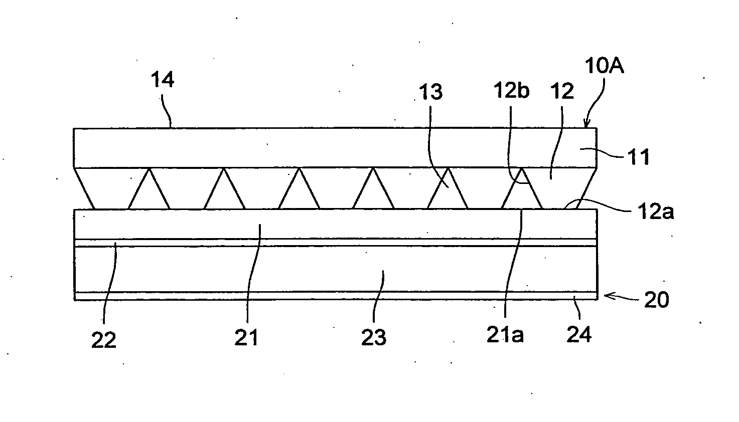
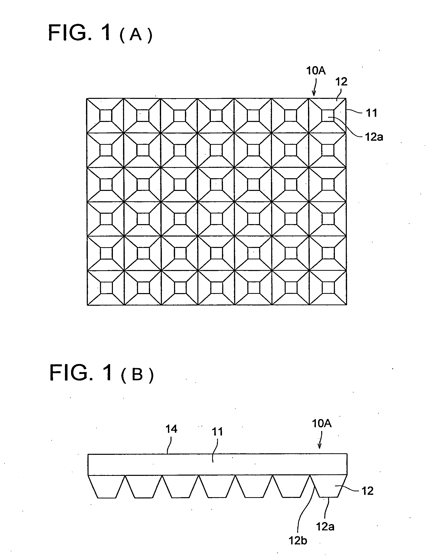
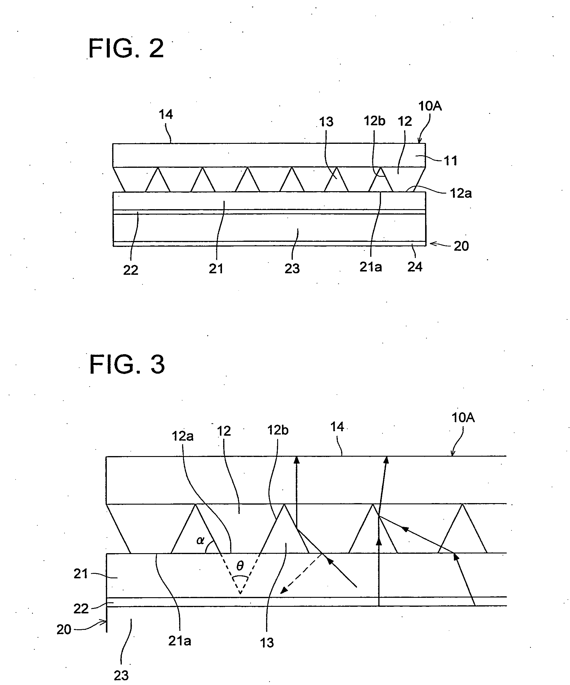
[0158] In the first implementation example, as was shown in the first preferred embodiment, a prism array sheet 10A was used which was a transparent substrate 11 on one surface of which truncated square pyramid shaped projections with shrunk tips were formed successively, and the tip surfaces 12a of the truncated square pyramid shaped projections 12 in this prism array sheet 10A are adhered to the light emitting side surface 21a of the surface light emitting device 20 of the comparison example 1. Further, the refractive index of this prism array sheet 10A was 1.495 for light of wavelength 550 nm, the apex angle θ of the truncated square pyramid shaped projections 12 was 60°, and if the pitch of the above truncated square pyramid shaped projections 12 is taken as 1, then the thickness of the above transparent substrate 11 was 2.6, the height of the truncated square pyramid shaped projections 12 was 0.45, and the pitch of the projections 12 was 100 μm.
implementation example 2
[0159] In the second implementation example, as was shown in the second preferred embodiment, a prism array sheet 10B was used which was a transparent substrate 11 on one surface of which a plurality of truncated square pyramid shaped projections with shrunk tips were formed successively with respective prescribed spacings in the lateral and longitudinal directions, and the tip surfaces 12a of the truncated square pyramid shaped projections 12 in this prism array sheet 10A are adhered to the light emitting side surface 21a of the surface light emitting device 20 of the comparison example 1. Further, the refractive index of this prism array sheet 10B was 1.495 for light of wavelength 550 nm, the apex angle θ of the truncated square pyramid shaped projections 12 was 60°, and if the pitch of the above truncated square pyramid shaped projections 12 is taken as 1, then the thickness of the above transparent substrate 11 was 2.6, the height of the truncated square pyramid shaped projectio...
PUM
 Abstract
Description
Claims
Application Information