Craniofacial implant

a technology of craniofacial implants and implants, which is applied in the field of craniofacial implants, can solve the problems of difficult internal bone repair and fixation problems, cancer, resection, or congenital defects, and the craniofacial and especially orbital wall and floor defects, etc., and achieve the effect of reducing the risk of fracture, re-shaping or ben

Active Publication Date: 2006-10-05
ORTHOVITA INC
View PDF98 Cites 213 Cited by
  • Summary
  • Abstract
  • Description
  • Claims
  • Application Information

AI Technical Summary

Benefits of technology

[0013] The present invention further provides a unique composite implant structure which can be shaped for use during a surgical procedures relating to the repair or fixation of the desired bones, and be readily cut, reshaped or bent to conform to the bones to be repaired. In a particular embodiment, the present invention provides an implant that can be used to repair the orbital walls and can be affixed to the orbit or the orbital margin.

Problems solved by technology

Craniofacial and especially orbital wall and floor defects may result from trauma, cancer, resection, or congenital defects.
Congenital defects or fractures of the complex and relatively thin bone structures surrounding and supporting the human eye present difficult internal bone repair and fixation problems.
However, compression of the orbital contents sometimes may occur and fracture the relatively fragile orbit floor and / or the lateral and medial orbital walls.
Also injury at the lateral orbital rim may produce a fracture within the orbit.
When the orbit is fractured standard bone-grafting techniques for orbital reconstruction may not result in predictable eye function and positioning.
Often the support of the globe is deficient as a result of under correction of the defect, over correction, or inadequate reconstruction of the orbital volume.
Further, the bone graph may be subject to resorption that may result in result in a less than optimal support.
Because most of the bone of the internal orbit surfaces is thin, it is difficult to adequately stabilize the fractured bone fragments without the use of autogenous or alloplastic materials.
Damage to other craniofacial bones and the cranium may also occur from many of the above-listed sources, perhaps trauma and congenital defects being the most common.
However, this material is sometimes difficult to obtain and difficult to shape the bone graft material to properly fit within the orbit or other area to be reconstructed.
For example, there are problems relating to the tissue donor site morbidity.
However, autogenous bones sometimes result in an unacceptable amount of resorption.
While there are advantages of synthetic implants, some characteristics may be regarded as disadvantages.
Silicone rubber has a smooth surface, but does not allow fibrovascular ingrowth into the implant.
Further, although it is flexible, it does not readily conform to the profile of the region where it is required or maintain a new shape when shaped to fit a particular location.
For example, in connection with the reconstruction of the orbit, a silicone rubber implant is not an attractive option because upon shaping it to the desired profile, it will tend to be biased back to its original shape.
Attachment of these tissues to the wall of the implant may result in restriction of movement of the eye, causing diplopia, dizziness, and headaches, as well as a cosmetic anomaly on upgaze, downgaze or lateral gaze.
Similar issues arise in connection with the repair of other craniofacial bones.
Further, using a material that does not have a smooth superior surface, may result in restriction of the orbital tissues due to fibrous ingrowth when used for orbital reconstruction.
Titanium mesh is easily moldable in situ and easily fixed to bone, but does not have smooth surfaces, nor does it allow for fibrovascular ingrowth.

Method used


Image

  • Craniofacial implant
  • Craniofacial implant
  • Craniofacial implant

Examples


Embodiment Construction

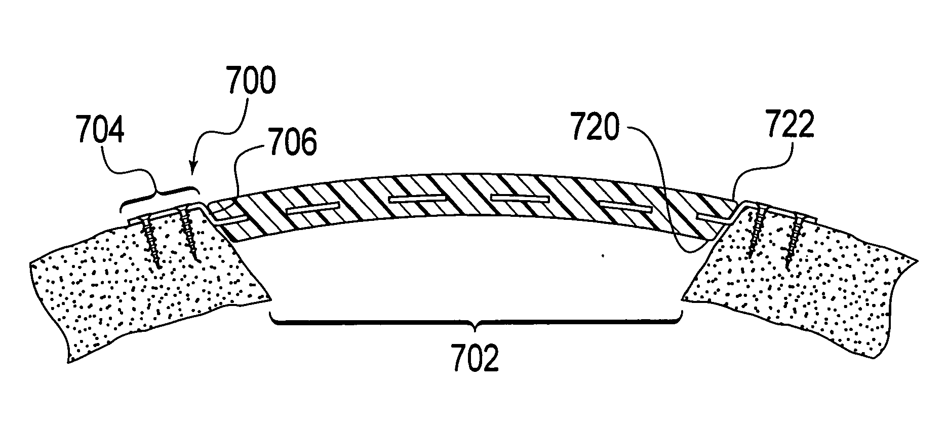
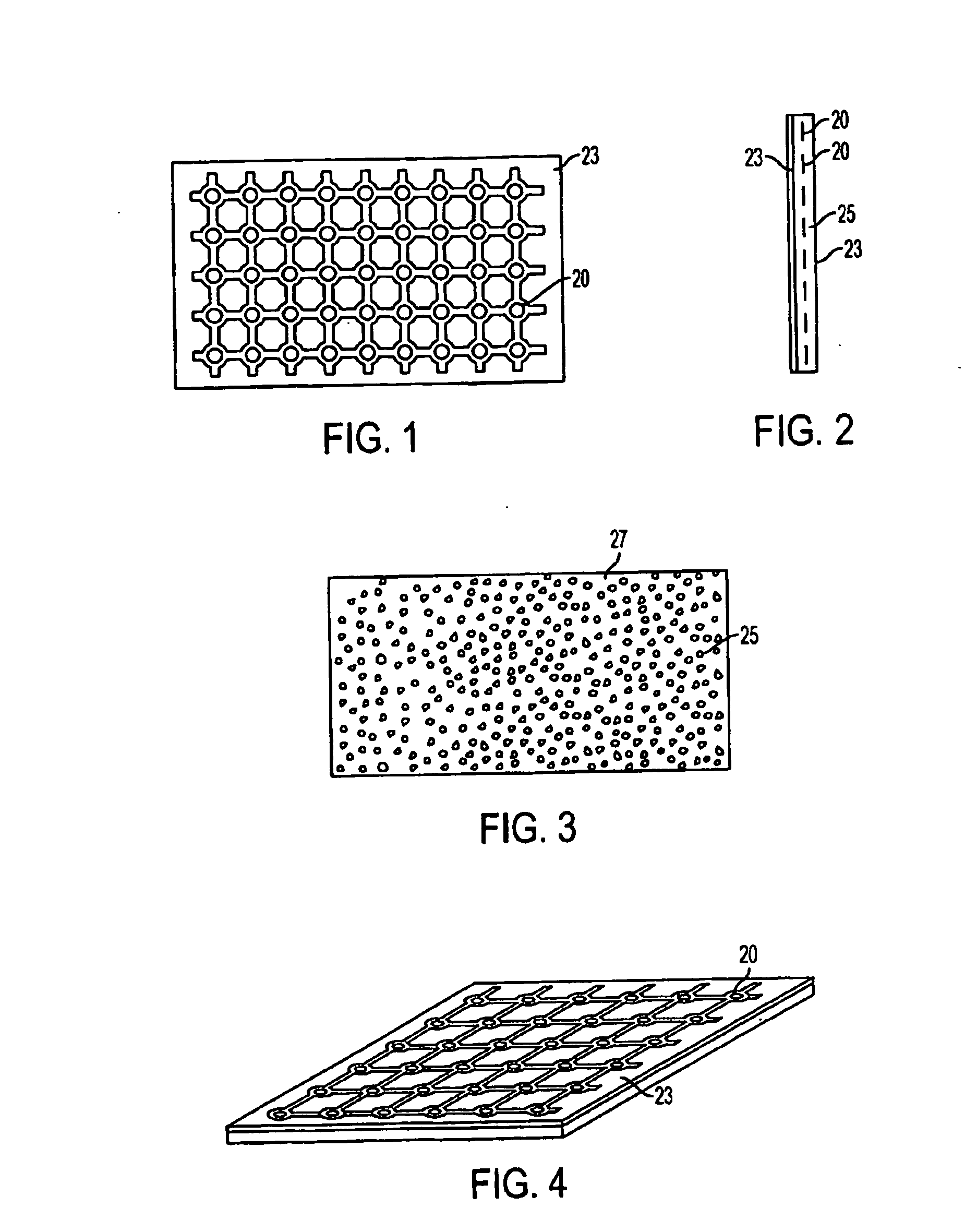
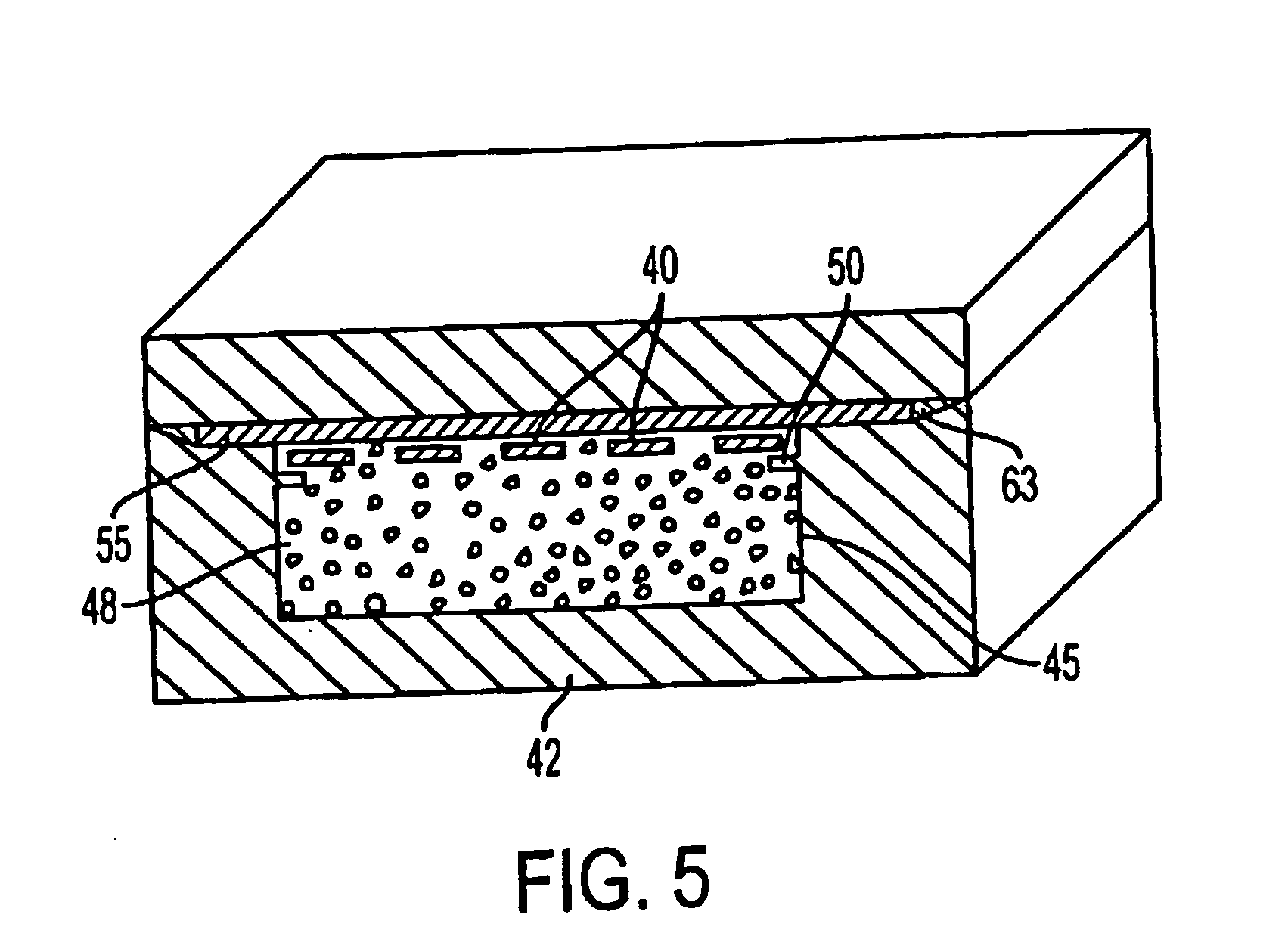
[0042] The present invention is directed to novel implants for craniofacial surgery, methods for making said implant, and methods of reconstructing orbital and cranial defects with the implants described. As described herein, one preferred application for the implant is for the reconstruction of orbital defects that may have resulted from trauma or disease or birth defects. Other craniofacial and cranial applications are also contemplated. The implants preferably have a mesh portion that is coated or covered with a smooth (or barrier) sheet on both sides of the mesh, a porous sheet on both sides of the mesh, or a smooth (or barrier) sheet on one side of the mesh and a porous sheet on the other side of the mesh.

[0043] A first embodiment of the invention comprises a sheet of mesh with a porous layer formed in the interstices of the mesh and at least partially or completely covering the bottom surface of the implant, and a solid sheet of film covering the top side of the implant. This...


PUM

PropertyMeasurementUnit
pore sizesaaaaaaaaaa
thickaaaaaaaaaa
thickaaaaaaaaaa

Abstract

A composite surgical implant that is made of a planar sheet of a thermoplastic resin that includes a top surface, a bottom surface, and a surgical grade metal mesh or metal plates contained therein. The implant may be bent by hand, wherein upon the displacement of the implant, the implant will generally maintain the shape to which it has been displaced.

Description

[0001] This application is a continuation-in part of U.S. application Ser. No. 10 / 517,843 titled “Craniofacial Implant” filed on Jul. 12, 2005, which is the national phase application of International Application No. PCT / US2004 / 011903 filed on Apr. 16, 2004, which claims priority to U.S. Application Nos. 60 / 463,036 and 60 / 496,684, filed on Apr. 16, 2003 and Aug. 21, 2003, respectively, the entire contents of each of which are incorporated by reference.BACKGROUND OF THE INVENTION [0002] Craniofacial and especially orbital wall and floor defects may result from trauma, cancer, resection, or congenital defects. Such defects are typically treated surgically using bone grafts or synthetic implants. Congenital defects or fractures of the complex and relatively thin bone structures surrounding and supporting the human eye present difficult internal bone repair and fixation problems. In instances when the eye is subject to trauma, the margin or rim of the orbit may diffuse the force of the ...

Claims


Application Information

Patent Timeline
Patent Type & Authority Applications(United States)
IPC IPC(8): A61F2/28A61B17/80
CPCA61B17/8085A61B17/86A61L27/56A61F2/2803A61F2/2875A61F2/30767A61F2/30965A61F2002/2878A61F2002/30065A61F2002/30092A61F2002/30578A61F2002/30677A61F2002/30787A61F2002/30957A61F2002/3096A61F2210/0014A61F2210/0071A61F2310/00017A61F2310/00023A61F2310/00323A61F2310/00407A61L27/446C08L23/06A61F2/02
Inventor SWORDS, GREGNOBLE, AARON M.
Owner ORTHOVITA INC
Why Eureka
Try Eureka