Craniofacial implant

a craniofacial implant and implant technology, applied in the field of can solve the problems of difficult internal bone repair and fixation problems, cancer, resection, or congenital defects, and craniofacial and especially orbital wall and floor defects

Active Publication Date: 2010-02-02
HOWMEDICA OSTEONICS CORP
View PDF92 Cites 83 Cited by
  • Summary
  • Abstract
  • Description
  • Claims
  • Application Information

AI Technical Summary

Benefits of technology

[0010]It is a further object of the invention to provide a unique composite implant structure which can be shaped for use during a surgical procedures relating to the repair of the orbit and be readily cut, reshaped or bent to conform to the orbital walls and affixed to the orbit or the orbital margin.
[0010]It is a further object of the invention to provide a unique composite implant structure which can be shaped for use during a surgical procedures relating to the repair of the orbit and be readily cut, reshaped or bent to conform to the orbital walls and affixed to the orbit or the orbital margin.
[0011]It is another object of the invention to provide an implant structure that forms a barrier between the sinus and the soft tissues of the orbit.
[0012]It is a further object of the invention to provide a craniofacial implant that may be used in other applications wherein it is desirable to maintain the shape of the implant.

Problems solved by technology

Craniofacial and especially orbital wall and floor defects may result from trauma, cancer, resection, or congenital defects.
Congenital defects or fractures of the complex and relatively thin bone structures surrounding and supporting the human eye present difficult internal bone repair and fixation problems.
However, compression of the orbital contents sometimes may occur and fracture the relatively fragile orbit floor and / or the lateral and medial orbital walls.
Also injury at the lateral orbital rim may produce a fracture within the orbit.
When the orbit is fractured standard bone-grafting techniques for orbital reconstruction may not result in predictable eye function and positioning.
Often the support of the globe is deficient as a result of under correction of the defect, over correction, or inadequate reconstruction of the orbital volume.
Further, the bone graph may be subject to resorption that may result in result in a less than optimal support.
Because most of the bone of the internal orbit surfaces is thin, it is difficult to adequately stabilize the fractured bone fragments without the use of autogenous or alloplastic materials.
However, this material is sometimes difficult to obtain and difficult to shape the bone graft material to properly fit within the orbit.
There are problems relating to the tissue donor site morbidity.
However, autogenous bones sometimes result in an unacceptable amount of resorption.
While there are advantages of synthetic implants, some characteristics may be regarded as disadvantages.
Silicone rubber has a smooth surface, but does not allow fibrovascular ingrowth into the implant.
Further, although it is flexible, it does not readily conform to the profile of the region where it is required or maintain a new shape when shaped to fit a particular location.
For example, in connection with the reconstruction of the orbit, a silicone rubber implant is not an attractive option because upon shaping it to the desired profile, it will tend to be biased back to its original shape.
Attachment of these tissues to the wall of the implant may result in restriction of movement of the eye, causing diplopia, dizziness, and headaches, as well as a cosmetic anomaly on upgaze, downgaze or lateral gaze.
Further, porous polyethylene does not have a smooth superior surface, so it may result in restriction of the orbital tissues due to fibrous ingrowth when used for orbital reconstruction.
Titanium mesh is easily moldable in situ and easily fixed to bone, but does not have smooth surfaces, nor does it allow for fibrovascular ingrowth.

Method used


Image

  • Craniofacial implant
  • Craniofacial implant
  • Craniofacial implant

Examples


Embodiment Construction

[0035]The present invention is directed to novel implants for craniofacial surgery, methods for making said implant and a method of reconstructing orbital and cranial defects with the implants described. As described herein, a preferred application for the implant is for the reconstruction of orbital defects that may have resulted from trauma or disease or birth defects. Other craniofacial applications are also contemplated.

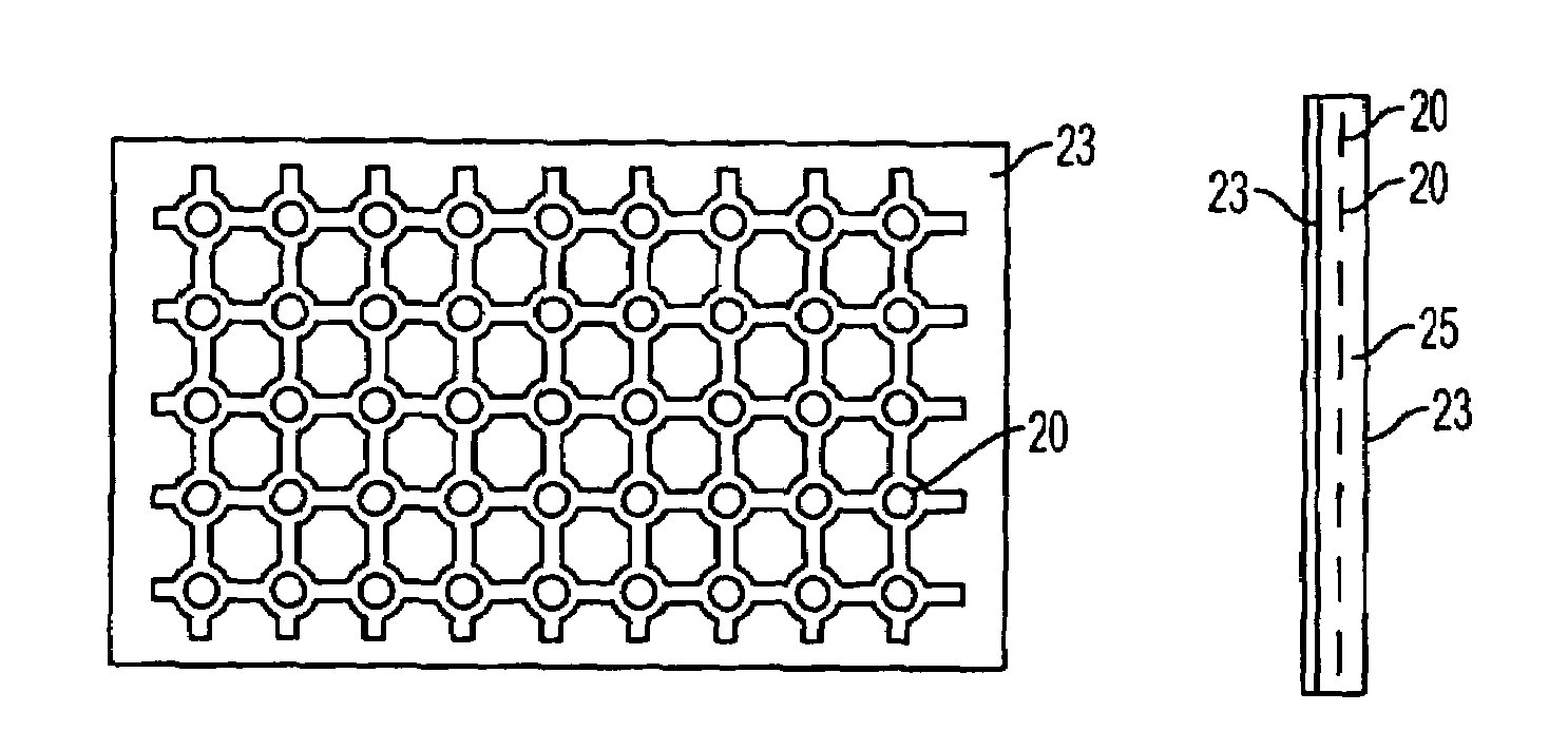
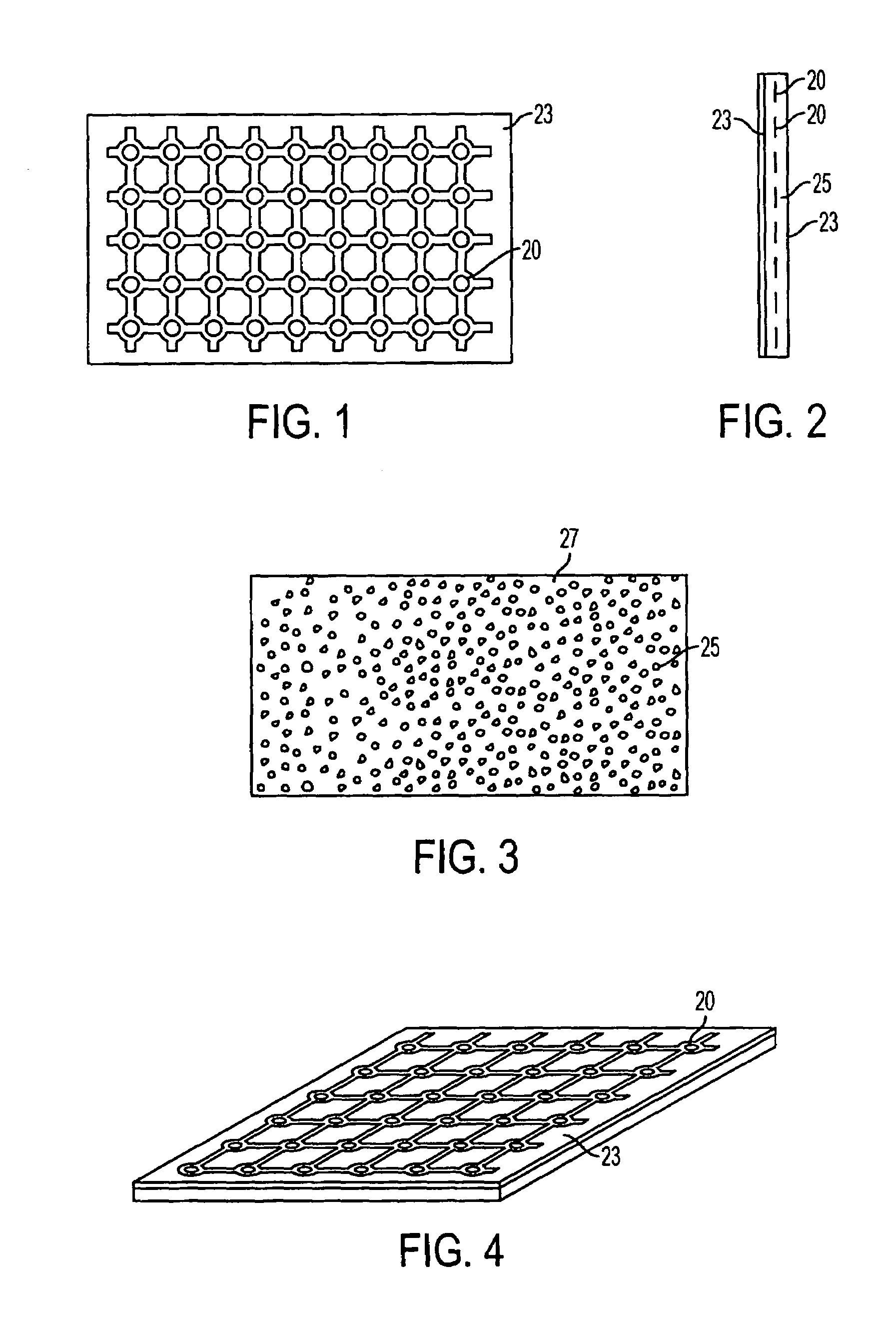
[0036]Now referring to FIG. 1, a first embodiment of the invention comprises a sheet of titanium mesh 20, with porous polyethylene formed in the interstices of the mesh and completely covering the bottom surface 27 of the implant. A solid sheet of polyethylene film 23 covers the top side of the implant. The mesh 20 provides for strength and serves to retain the shape of the implant in a rigid and fixed position. It should be understood that a mesh as used herein encompass any flat sheet of surgical grade metal that has perforations or passages formed through the ...


PUM

PropertyMeasurementUnit
thickaaaaaaaaaa
thickaaaaaaaaaa
thickaaaaaaaaaa

Abstract

A composite surgical implant that is made of a planar sheet of a thermoplastic resin that includes a top surface (400), a bottom surface (410), and a surgical grade metal mesh (405) contained therein. The implant may be bent by hand, wherein upon the displacement of the implant, the implant will generally maintain the shape to which it has been displaced.

Description

[0001]The applicant claims the benefit U.S. Application Nos. 60 / 463,036 and 60 / 496,684.BACKGROUND OF THE INVENTION[0002]Craniofacial and especially orbital wall and floor defects may result from trauma, cancer, resection, or congenital defects. Such defects are typically treated surgically using bone grafts or synthetic implants. Congenital defects or fractures of the complex and relatively thin bone structures surrounding and supporting the human eye present difficult internal bone repair and fixation problems. In instances when the eye is subject to trauma, the margin or rim of the orbit may diffuse the force of the impact. However, compression of the orbital contents sometimes may occur and fracture the relatively fragile orbit floor and / or the lateral and medial orbital walls. Also injury at the lateral orbital rim may produce a fracture within the orbit. When the orbit is fractured standard bone-grafting techniques for orbital reconstruction may not result in predictable eye fu...

Claims


Application Information

Patent Timeline
Patent Type & Authority Patents(United States)
IPC IPC(8): A61F2/02A61B17/80A61F2/00A61F2/28A61F2/30A61L27/44
CPCA61B17/8085A61F2/2875A61F2/30965A61L27/446C08L23/06A61F2002/30535A61F2002/2878A61F2250/0058A61F2/02A61F2/28A61L27/00A61L27/44
Inventor SWORDS, GREG
Owner HOWMEDICA OSTEONICS CORP
Why Eureka
Try Eureka