Craniofacial implant

Active Publication Date: 2005-12-29
ORTHOVITA INC
View PDF66 Cites 66 Cited by
  • Summary
  • Abstract
  • Description
  • Claims
  • Application Information

AI Technical Summary

Benefits of technology

[0014] The present invention is directed to an improved implant and method of reconstruction of craniofacial defects, and in particular for orbital defects. The implant is a composite structure comprised of a surgical grade metal provided in a planar sheet form that is encased within a thermoplastic resin. In a first embodiment, one surface of the implant is smooth and impervious so that when the implant is placed within the body, it may form a barrier. In an alternative embodiment of

Problems solved by technology

Craniofacial and especially orbital wall and floor defects may result from trauma, cancer, resection, or congenital defects.
Congenital defects or fractures of the complex and relatively thin bone structures surrounding and supporting the human eye present difficult internal bone repair and fixation problems.
However, compression of the orbital contents sometimes may occur and fracture the relatively fragile orbit floor and/or the lateral and medial orbital walls.
Also injury at the lateral orbital rim may produce a fracture within the orbit.
When the orbit is fractured standard bone-grafting techniques for orbital reconstruction may not result in predictable eye function and positioning.
Often the support of the globe is deficient as a result of under correction of the defect, over correction, or inadequate reconstruction of the orbital volume.
Further, the bone graph may be subject to resorption that may result in result in a less than optimal support.
Because most of the bone of the internal orbit surfaces is thin, it is difficult to adequately stabilize the fractured bone fragments without the use of autogenous or alloplastic materials.
However, this material is sometimes difficult to obtain and difficult to shape the bone graft material to properly fit within the orbit.
Th

Method used


Image

  • Craniofacial implant
  • Craniofacial implant
  • Craniofacial implant

Examples


Embodiment Construction

[0035] The present invention is directed to novel implants for craniofacial surgery, methods for making said implant and a method of reconstructing orbital and cranial defects with the implants described. As described herein, a preferred application for the implant is for the reconstruction of orbital defects that may have resulted from trauma or disease or birth defects. Other craniofacial applications are also contemplated.

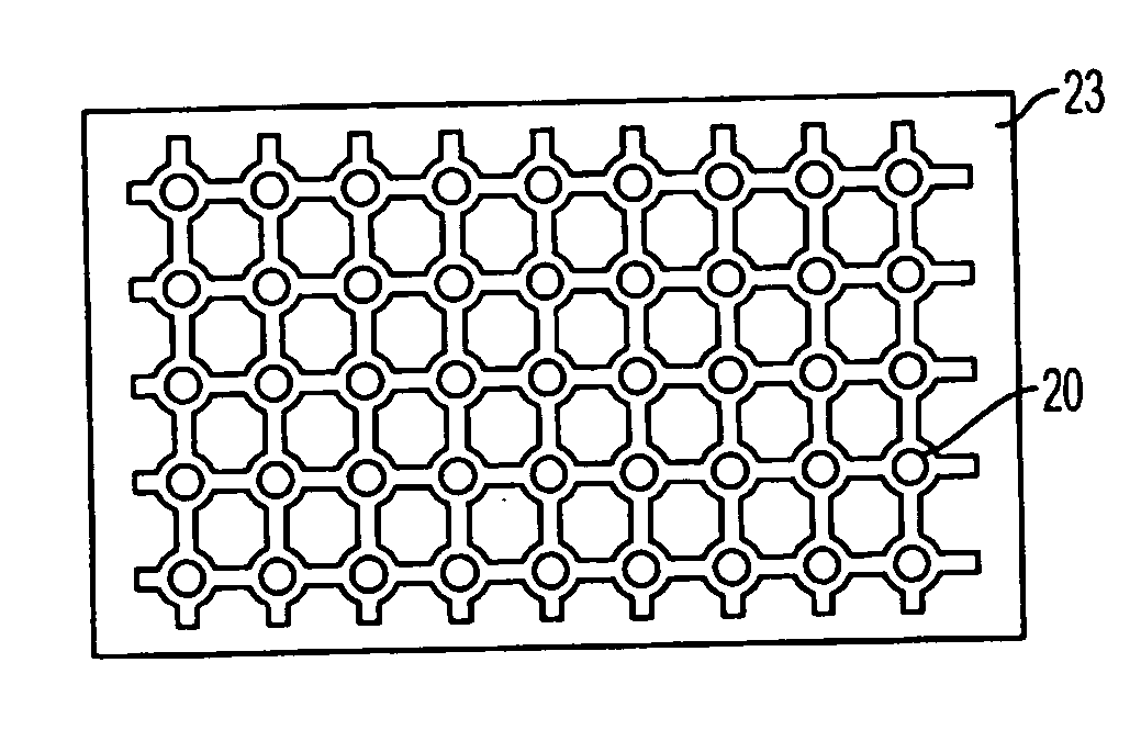
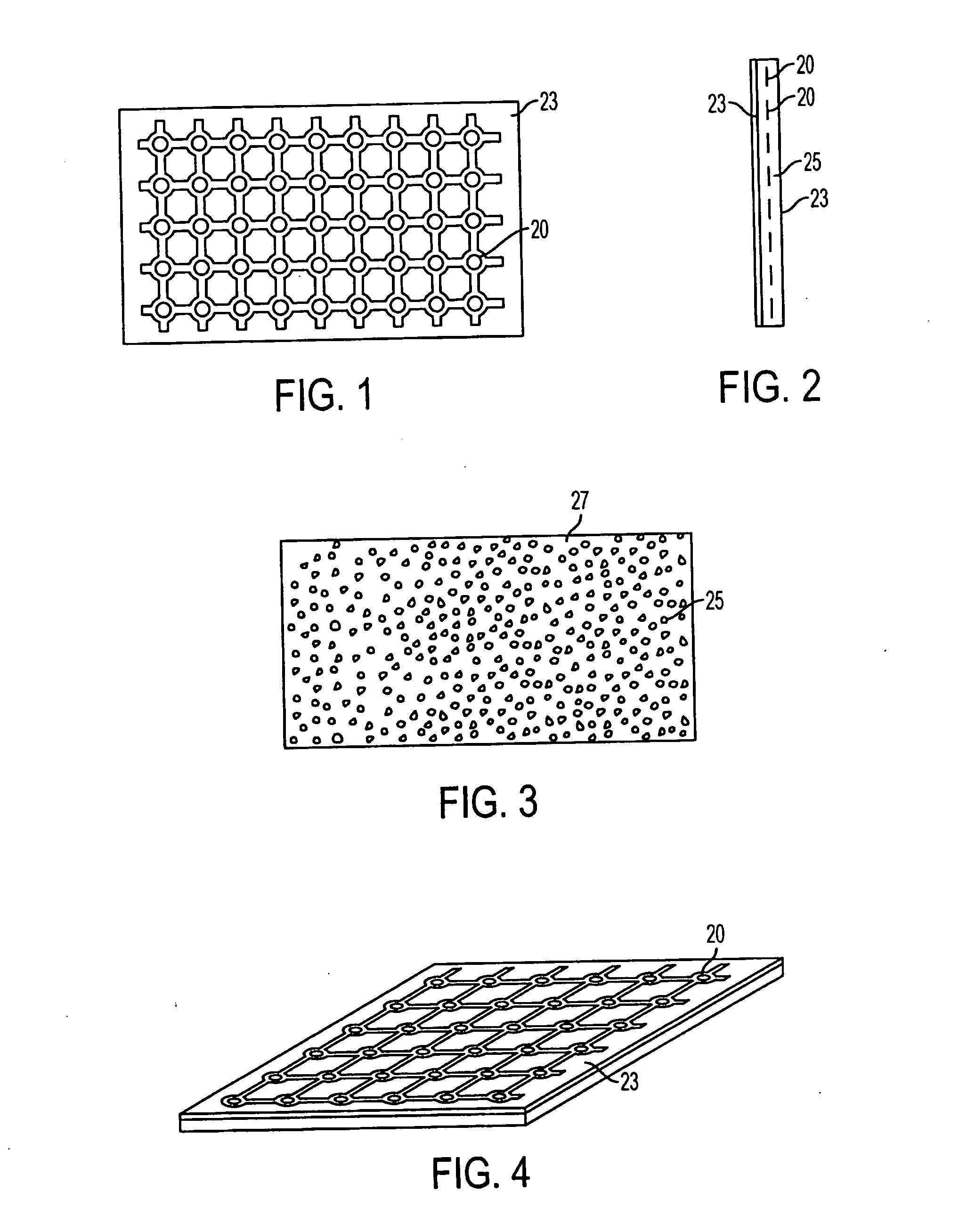
[0036] Now referring to FIG. 1, a first embodiment of the invention comprises a sheet of titanium mesh 20, with porous polyethylene formed in the interstices of the mesh and completely covering the bottom surface 27 of the implant. A solid sheet of polyethylene film 23 covers the top side of the implant. The mesh 20 provides for strength and serves to retain the shape of the implant in a rigid and fixed position. It should be understood that a mesh as used herein encompass any flat sheet of surgical grade metal that has perforations or passages formed through t...


PUM

PropertyMeasurementUnit
Pressureaaaaaaaaaa
Densityaaaaaaaaaa
Shapeaaaaaaaaaa

Abstract

A composite surgical implant that is made of a planar sheet of a thermoplastic resin that includes a top surface (400), a bottom surface (410), and a surgical grade metal mesh (405) contained therein. The implant may be bent by hand, wherein upon the displacement of the implant, the implant will generally maintain the shape to which it has been displaced.

Description

[0001] The applicant claims the benefit U.S. Application Nos. 60 / 463,036 and 60 / 496,684.BACKGROUND OF THE INVENTION [0002] Craniofacial and especially orbital wall and floor defects may result from trauma, cancer, resection, or congenital defects. Such defects are typically treated surgically using bone grafts or synthetic implants. Congenital defects or fractures of the complex and relatively thin bone structures surrounding and supporting the human eye present difficult internal bone repair and fixation problems. In instances when the eye is subject to trauma, the margin or rim of the orbit may diffuse the force of the impact. However, compression of the orbital contents sometimes may occur and fracture the relatively fragile orbit floor and / or the lateral and medial orbital walls. Also injury at the lateral orbital rim may produce a fracture within the orbit. When the orbit is fractured standard bone-grafting techniques for orbital reconstruction may not result in predictable eye...

Claims


Application Information

Patent Timeline
IPC IPC(8): A61B17/80A61F2/00A61F2/28A61F2/30A61L27/44
CPCA61B17/8085A61F2/2875A61F2/30965A61F2002/30535A61F2002/2878A61L27/446A61F2250/0058C08L23/06A61F2/02A61F2/28A61L27/00A61L27/44
Inventor SWORDS, GREG
Owner ORTHOVITA INC
Why Eureka
Try Eureka