Prosthetic hand having a conformal, compliant grip and opposable, functional thumb

a technology of prosthetic hands and thumbs, applied in the field of prosthetic hands, can solve the problems of limited range of opening the hook in order to grasp an object, loss of ‘good view’ quality of split hooks, and still the same usability problems

Inactive Publication Date: 2006-10-05
WINFREY REX CLAYTON
View PDF3 Cites 73 Cited by
  • Summary
  • Abstract
  • Description
  • Claims
  • Application Information

AI Technical Summary

Benefits of technology

[0020] It is a further object of the invention that this compliance will not cause the hand or fingers to malfunction in any manner.
[0021] It is a further object of the invention that the fingers have a conformal grip. This grip allows one or all fingers to fully close onto an object regardless of the position of the other fingers.

Problems solved by technology

U.S. Pat. No. 5,219,366, while having several grasping surfaces, lost the ‘good view’ quality of the split hook.
The biggest drawback to the split hook is the limited range that the hook can be opened in order to grasp an object.
They still have the same usability problems that the split hook has.
Objects with a complex, or a tapered shape can not be held securely, and sometimes not at all.
This is virtually useless for prosthetics.
The overall bulk of the claw would prevent most amputees from using it, and again, tapered objects can not be held securely.
This one in particular would probably damage most objects it attempts to pick up.
There is no opposition contact possible with the two halves of the claw.
Like the others, it is very limited in what it is able to grasp.
Driving a rotating force with a cable is a poor choice when the cable is bent while driving the force.
The cables tend to develop torque induced twist that will cause the ‘externally threaded cinctures’ to bind in the bushings as well as the destruction of the cable.
The fingers will not be able to conform to the object being grasped.
This will result in a small surface contact area being used for any object that does not perfectly fit into the designed curve of the fingers.
If the fingers do not make contact with the object at the same time, this linkage design will not allow for the torque loads that would be placed on parts 65 and 66.
This would render the hand nonfunctional.
The use of two tendons is actually useless, as the cable that operates one, operates the other in the exact amount.
Unfortunately the fingers must either be operated by one motor, or by a motor for each finger.
The other channels would have to be driven by separate myoelectric sensors, which is not plausible due to the limits of how many suitable sites can be found on the body that would not cause excessive cross talk interference between each channel.
The cable system of this hand also has inherent problems.
The larger problem with the dual cable system has to do with excessive slack, or tension in the cables.
This would either cause an excessive amount of slack, or tension in the cables.
Excessive slack would allow the cables to slip off the reels, requiring the hand to need repair work.
Excessive tension could cause damage to the cables, or the fingers, or the shaft and reels.
This hand may well be usable for robotics, but is not satisfactory for prosthetics.
U.S. Pat. No. 4,986,723 also has the problem of too many control channels.
It also has a very large number of parts that can fail, resulting in excessive maintenance.
So they are less likely to come off the pulleys, but may slip on the pulleys, causing the sections of the fingers to get ‘out of sync’ with the other parts.
This design also requires a large number of motors to operate it.
Even if enough control channels were available for such prosthesis, the weight of the motors, and required power supply would prevent its use.
U.S. Pat. No. 5,080,682 has the problem also of too many motors needed to operate it, and the control channels needed to drive them.
As it is easier to pull a chain than push it, this method of moving the fingers would fail, and be damaged at the slightest amount of pressure on the fingers.
The ‘push rod’ (item 30) if flexible enough to bend around the fingers, would also be flexible enough to bend off line of its intended path, resulting in no movement of the finger, and possibly damage to the push rod.
Again, there are too many control channels, and too much weight in the drive system.
The fingers have compliance to external flexing forces, with out apparent damage happening.
The lack of a functional thumb is a draw back.

Method used


Image

  • Prosthetic hand having a conformal, compliant grip and opposable, functional thumb
  • Prosthetic hand having a conformal, compliant grip and opposable, functional thumb
  • Prosthetic hand having a conformal, compliant grip and opposable, functional thumb

Examples


Embodiment Construction

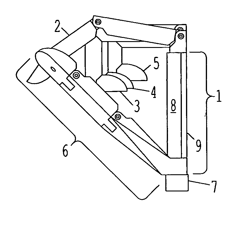
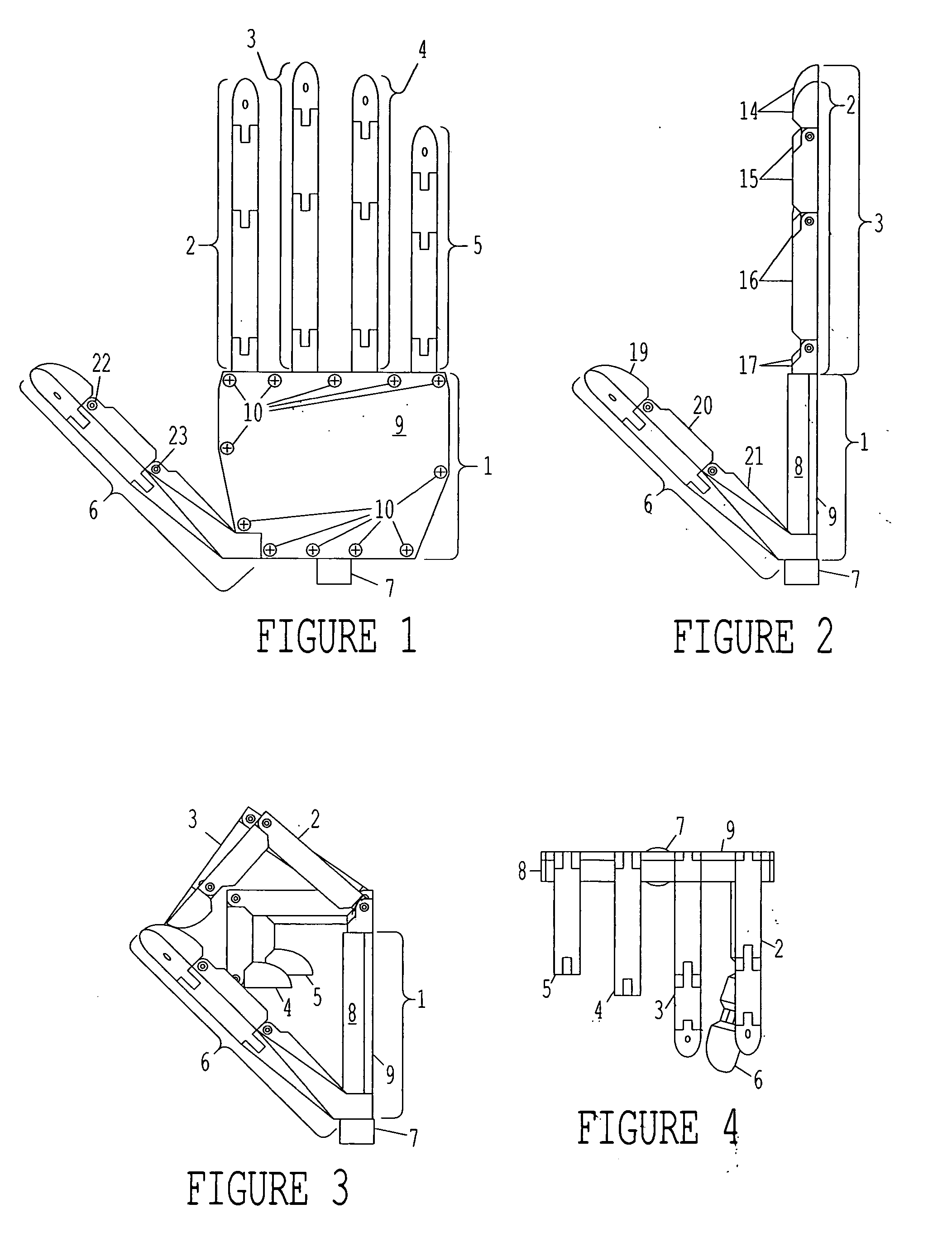
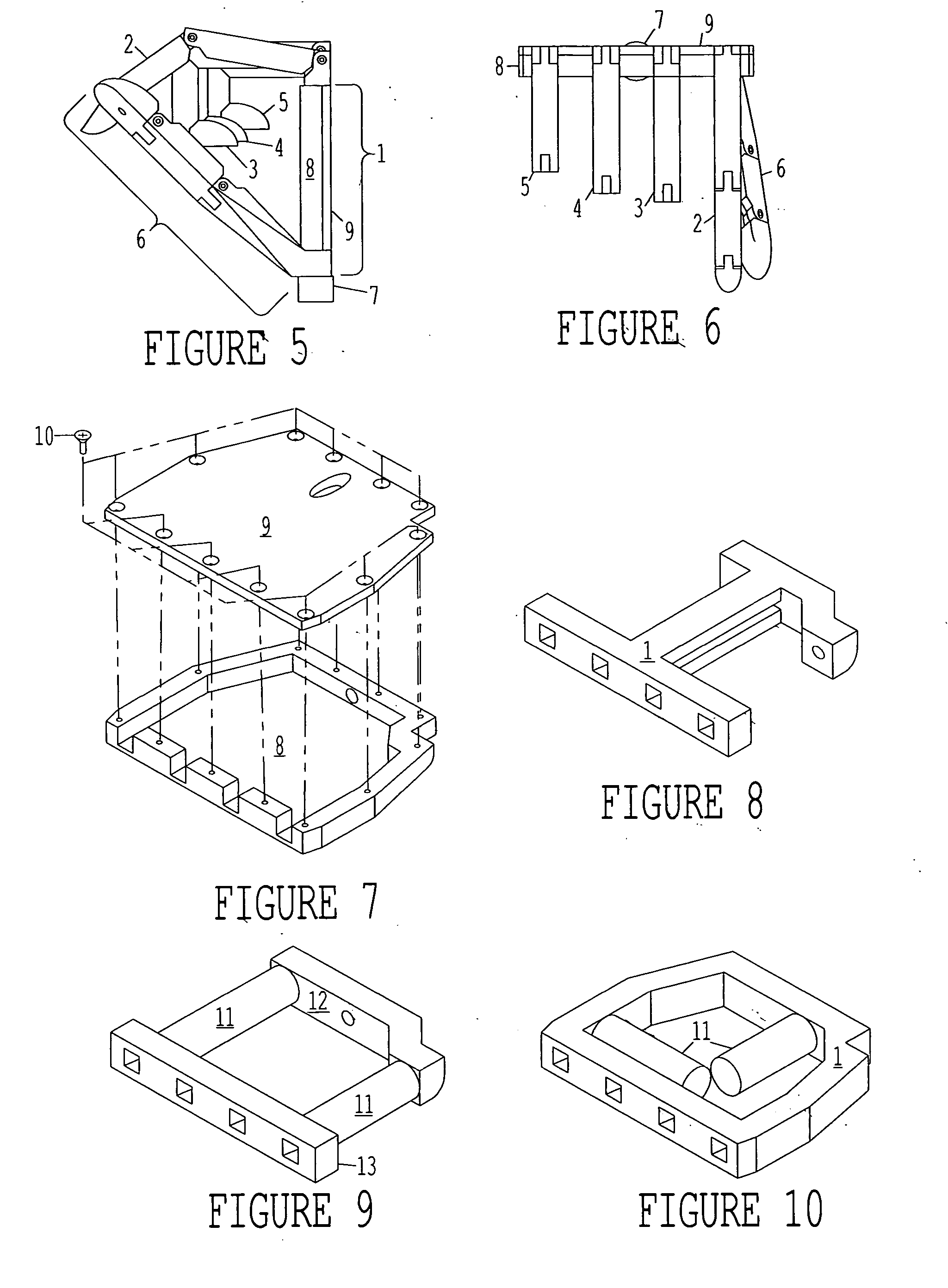
[0058] As seen in FIG. 1, the hand is made up of 7 distinct parts. Item 1 forms the frame of the hand. This frame (1) provides for the attachment of the fingers (2, 3, 4, 5), and the thumb (6). The frame (1) also contains the mechanism that allows the self biasing between the fingers (2-5), part of the hinge that allows opposition of the thumb (6), and the socket attachment point (7), allowing the amputee to wear the device. The attachment point (7) is a threaded piece of material that conforms to the standard attachment methods currently in use.

[0059] The thumb (6) can be rotated in opposition to the fingers (2, 3, 4, 5) as seen in FIG. 2. The thumb (6) and fingers (2, 3, 4, 5) are self-biasing to allow conformal grip. This will be explained in detail in later paragraphs. FIGS. 3 and 4 show the hand in a “clutching” position. The thumb (6) is rotated into opposition to the fingers (2, 3, 4, 5), and flexed, and the fingers (2, 3, 4, 5) are flexed to make contact with the thumb (6)....


PUM


Abstract

An anthropomorphic artificial hand having a mechanical system that allows for the digits to be compliant to pressure that tends to flex the digits, and provides for the digits to be self biasing to conform to the shape of the object being grasped. The hand comprises one to four fingers, with the fingers having up to three joints each. The hand may also comprise a thumb that can be rotated into and out of opposition of the fingers. The joints of the thumb are also self biasing to allow conformance to the object being grasped. The hand is of the voluntary closing operation, with all digits being self extending. This allows the hand to use two cables to operate if body powered (one for the fingers, one for the thumb). The hand may also be electronically powered using two channels for operating the fingers and thumb simultaneously.

Description

CROSS-REFERENCE TO RELATED APPLICATIONS [0001] Not Applicable STATEMENT REGARDING FEDERALLY SPONSORED RESEARCH OR DEVELOPMENT [0002] Not Applicable BACKGROUND OF THE INVENTION [0003] This invention relates to a prosthetic hand and more specifically to an anthropomorphic hand providing for a conformal, compliant grip and having an opposable functional thumb. (This is the patent offices preferred method of description.) [0004] From the time the first human survived an amputation, man has tried to make replacement body parts. The first replacement for an upper extremity amputation that seemed to be useful was the famous hook. It allowed the amputee to hold an object down, and pull it to them. If the object could be stabbed without ruining it, the amputee could pick up the object. The hook was slightly more useful than just using the stump. [0005] The next successful prosthesis is the split hook. There have been many specific designs for the split hook, but they are functionally the sam...

Claims


Application Information

Patent Timeline
Patent Type & Authority Applications(United States)
IPC IPC(8): A61F2/54
CPCA61F2/583A61F2/586A61F2/68B25J15/0009A61F2002/587A61F2002/701B25J9/104A61F2002/5093A61F2/70
Inventor WINFREY, REX CLAYTON
Owner WINFREY REX CLAYTON
Why Eureka
Try Eureka