Device for an industrial robot

a robot and industrial technology, applied in the field of industrial robots, can solve the problems of not being able to determine the maximum angle of relative rotation of parts and changing this angle, the means for fixing blocks to the first parts, for example a robot arm or a robot foot, may be in the form of bolts, and are subject to very considerable loads, so as to achieve simple and inexpensive manufacturing processes, the effect of simple mounting of stop elements

Inactive Publication Date: 2006-10-05
ABB (SCHWEIZ) AG
View PDF14 Cites 14 Cited by
  • Summary
  • Abstract
  • Description
  • Claims
  • Application Information

AI Technical Summary

Benefits of technology

[0007] Since the stop elements in this way act as if they were one single stop element, the force transmitted to them via the stop may be taken up by considerably more fixing means, for example screws, than if the stop elements should act as individual parts. Thus, the tangential force arising upon impact of the front stop element in the row against the stop will be capable of being transmitted from one stop element to another stop element and hence, to the greatest possible extent, the force be transmitted to the body of the first part that the stop elements are fixed to. This implies that the fixing means are spared great shear stresses in a radial direction, so that they do not have to be oversized or be reinforced by radial supports for the stop elements.
[0008] According to a preferred embodiment of the invention, said connection members are arranged, when forming said row, to bring about mechanical interlocking between adjacent stop elements. This makes possible a simple mounting of the stop elements in situ while at the same time achieving a reliable and effective locking of the elements so as to act, with respect to the force transmitted via the stop, as one single element. This also makes it possible to use simple and inexpensive manufacturing processes both for the stop elements and the surface on which they are intended to be screwed to the first part.
[0009] According to another preferred embodiment of the invention, the connection members comprise tooth-shaped projections on those surfaces of the stop elements which are essentially tangentially directed when a row has been formed, and recesses corresponding thereto in corresponding surfaces on adjacent stop elements. This constitutes a very simple and efficient way of forming said interlocking. In addition, the assembly is very simple in that adjacent stop elements may be pushed in an essentially tangential direction with the teeth and recesses into each other before being fixed to the first part.

Problems solved by technology

Admittedly, these devices enable moving the stop element along the first part, but a disadvantage thereof is that they do not allow defining the maximum angle for relative rotation of the parts and changing this angle, through opposite end surfaces of the stop element itself.
However, the means for fixing these blocks to the first part, for example a robot arm or a robot foot, which may be in the form of bolts, are subjected to very considerable loads when the first stop element, viewed in the direction of movement, is at some time run against the fixed stop.
It is both complicated and costly to arrive at such solutions to the problem of transmitting the impact forces to the fixing means of the stop elements.

Method used


Image

  • Device for an industrial robot
  • Device for an industrial robot
  • Device for an industrial robot

Examples


Embodiment Construction

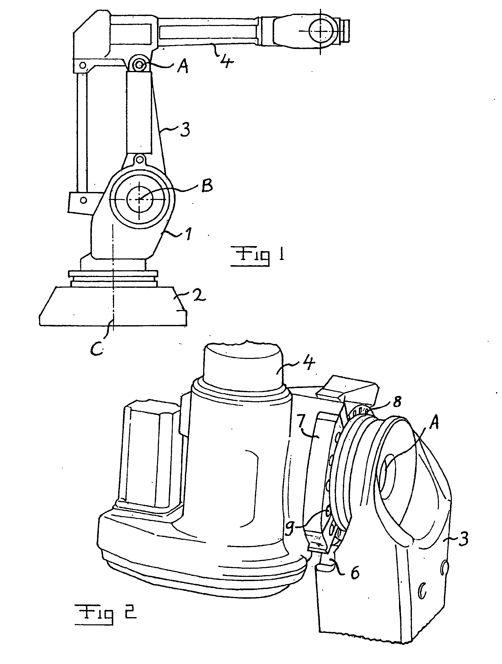
[0019]FIG. 1 shows one possible type of industrial robot, to which a device for restriction of the working range according to the invention may be applied. The robot has a stand 1 which is rotatably journalled, around a vertical axis C, in a robot foot 2 secured to a mounting base. A first robot arm 3 is pivotally journalled at the stand 1 around an axis B. At the upper end of the arm 3, a second robot arm 4 is pivotally journalled around an axis A.

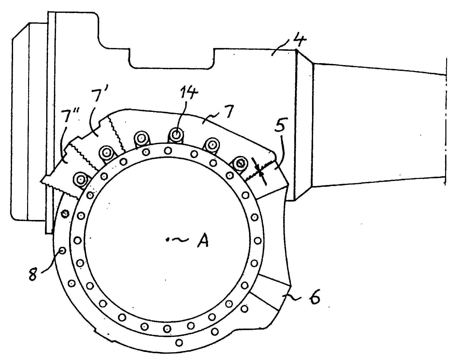
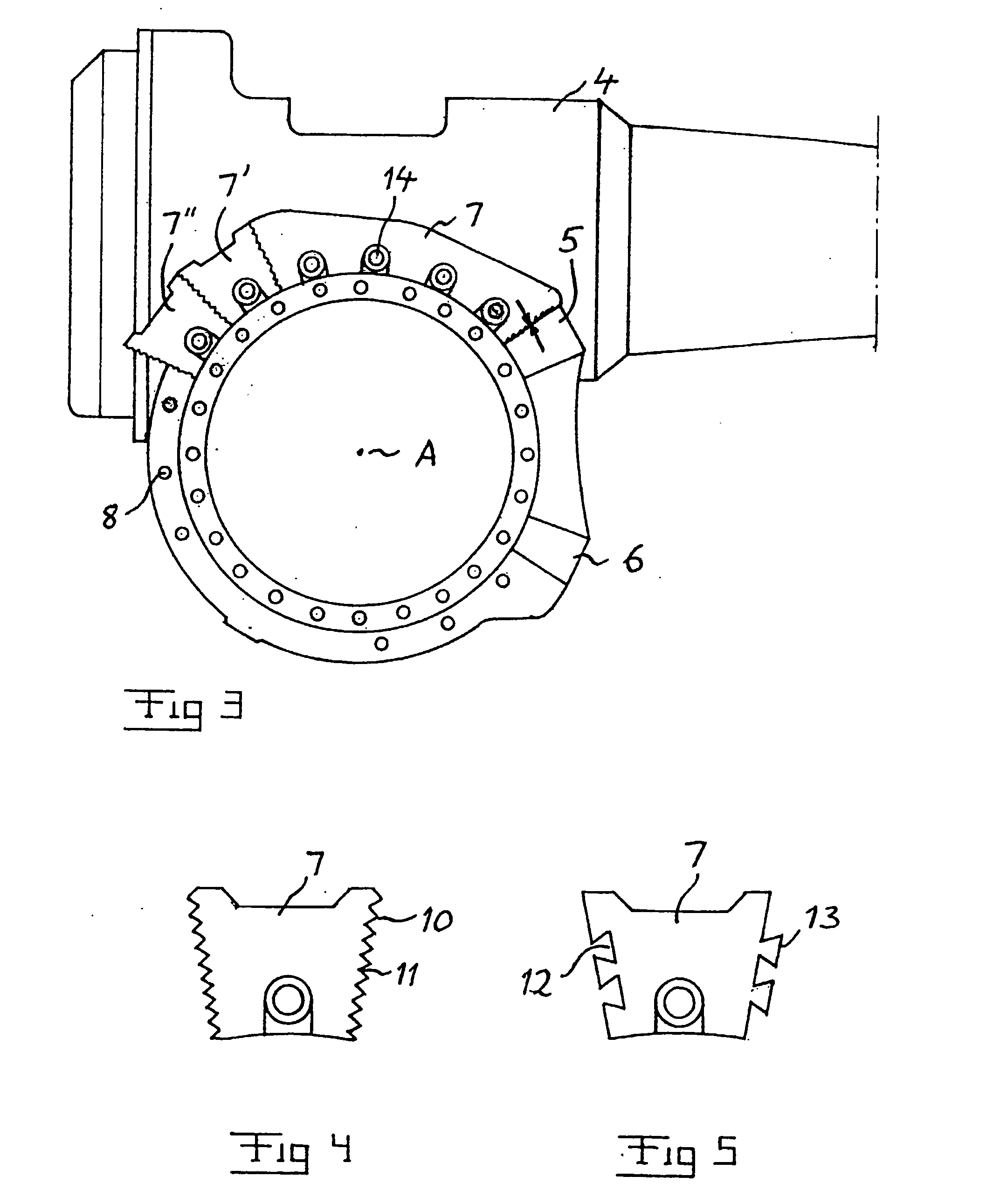
[0020] The working ranges of the axes A, B and C are restricted, for safety reasons, with the aid of mechanical or electrical stop means, such as a mechanical stop means of the kind to which the present invention relates and which will be described hereinafter while at the same time referring to FIGS. 2 and 3.

[0021]FIG. 2 illustrates how a device according to the invention is arranged for restricting the working range in the form of the maximum angle for rotation of an upper robot arm 4 relative to a lower robot arm 3 around an axis A. ...


PUM


Abstract

A device for restricting the working range around an axis of an industrial robot in the form of restriction of the maximum angle for rotation of the first part of the robot relative to a second part thereof, connected to the first part. The robot includes a fixed stop arranged at the second part, wherein the device includes a set of stop elements and aspects for fixing an optional number of stop elements on the first part in a row one after the other and making contact with one another along a circular arc around the axis of rotation of the first part, in order to hit against the stop with those end surfaces of the stop elements which are located on opposite ends of the row, when rotating the first part relative to the second part, thus forming opposite end positions for this rotation. The device includes members for such a mutual connection of stop elements arranged adjacent to each other in the row that these elements, with respect to the transmission of forces between them and the stop, when hitting against the latter upon the rotation, essentially behave as if they together were one single coherent stop element.

Description

TECHNICAL FIELD AND BACKGROUND ART [0001] The present invention relates to the field of devices for restricting the working range around an axis of an industrial robot in the form of restriction of the maximum angle for rotation of a first part of the robot relative to a second part connected to the first part, wherein the first part is provided with a stop and the second part is provided with a stop element adapted to hit against the stop, when rotating the first part relative to the second part, thus forming opposite end positions for this rotation. The industrial robot may be of any type. [0002] An industrial robot is usually programmed to operate within a certain working range. For safety reasons, it is furthermore often prescribed that the working range for certain axes of the robot shall be restricted, from the hardware point of view, by means of mechanical or electric stop means. In this way, an emergency stop of the robot is released if the robot, due to a fault in the contr...

Claims


Application Information

Patent Timeline
Patent Type & Authority Applications(United States)
IPC IPC(8): G06F19/00B25J9/10
CPCB25J9/101
Inventor HELDESJO, MAGNUSLUNDBACK, DANIEL
Owner ABB (SCHWEIZ) AG
Why Eureka
Try Eureka