Spraying device

a technology of a nozzle and a nozzle head, which is applied in the direction of liquid fuel feeders, generators/motors, machines/engines, etc., can solve the problems of ineffective spraying, waste of energy, and loss of vibrational energy, and achieve the effect of reducing energy consumption and more effective spraying

Active Publication Date: 2006-10-12
IND TECH RES INST
View PDF13 Cites 18 Cited by
  • Summary
  • Abstract
  • Description
  • Claims
  • Application Information

AI Technical Summary

Benefits of technology

[0007] It is an object of the present invention to provide a spraying device in which the vibrating element and liquid to be sprayed are insulated from each other, so that more effective spraying and reduced energy consumption are achieved.
[0008] Another object of the present invention is to provide a spraying device which is easily dismountable by using clamps or threads.

Problems solved by technology

Therefore, the liquid is driven indirectly by the vibrating plate, resulting in losses of vibrational energy, waste of energy and ineffective spraying.
Furthermore, conventional spraying devices are usually dismountable, so that upon a defect whole spraying devices have to be replaced, which is wasteful.

Method used


Image

  • Spraying device
  • Spraying device
  • Spraying device

Examples


second embodiment

[0017] Referring to FIG. 5, in the present invention, the cylinder 41 has an inner side with an inner thread 44 and the container 50 close to the neck 51 has a periphery with an outer thread 53, allowing to screw the fastening cap 40 on the container 50.

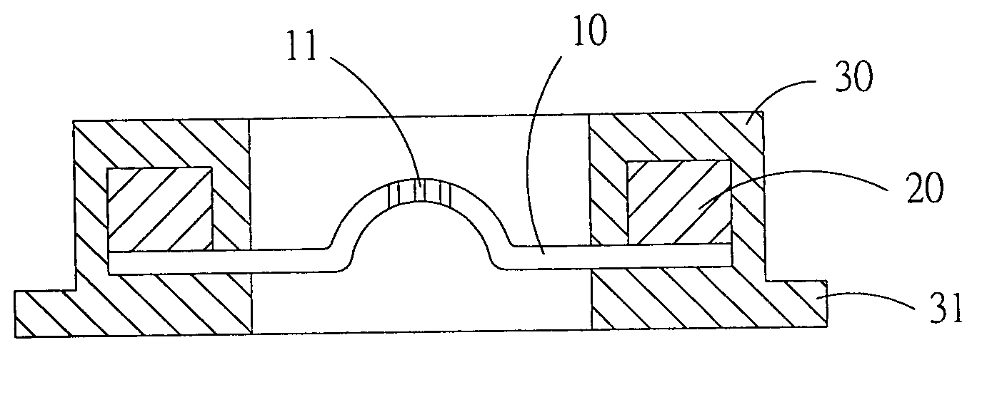
[0018] Since the fastening cap 40 provides for easy fastening of the spraying plate 10, the vibrating element 20 and the wrapping layer 30 on the neck 51 of the container 50, damaging of one of the structural parts of the spraying device of the present invention does not require replacing of the entire spraying device, avoiding waste and saving cost.

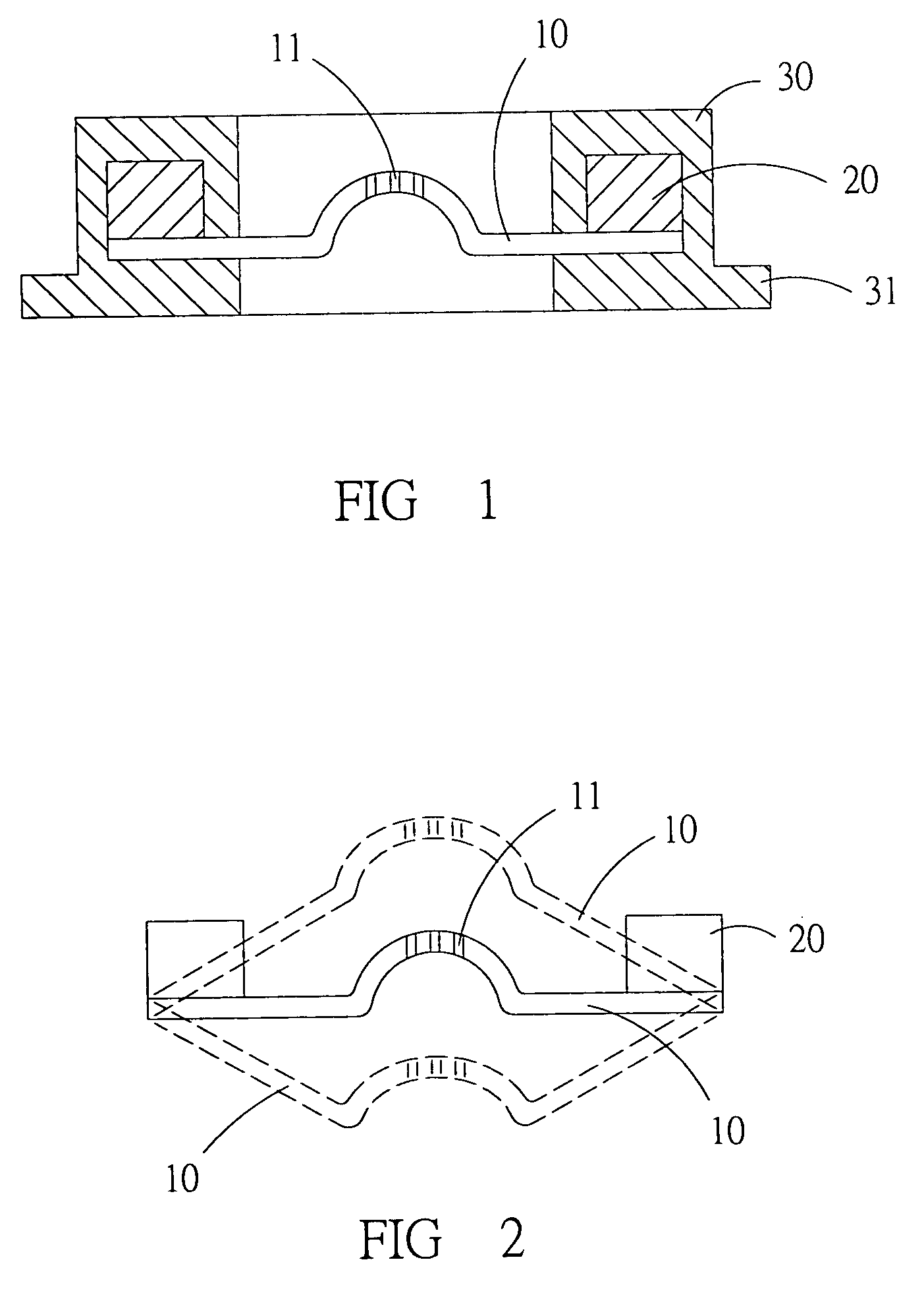
[0019] Furthermore, easy dismounting and remounting of the fastening cap 40 allows for quick adaption to different standards and requirements, including different diameters of sprayed micro-droplets and different rates of outflow of liquid, which are met by mounting another spraying plate 10 with a different number of spraying holes 11 of different diameters.

BRIEF DESCRIPTION OF THE DRA...

first embodiment

[0023]FIG. 4 is a sectional side view of the present invention in the

[0024]FIG. 5 is a sectional side view of the present invention in the second embodiment.


PUM


Abstract

A spraying device comprises a spraying plate, having a plurality of tiny holes, a vibrating element, set on a periphery of the spraying plate, and driving a vibrating movement thereof, a wrapping layer, made of soft material and tightly surrounding the vibrating element, sealing the vibrating element from the liquid, and a fastening cap, allowing for quick mounting and dismounting of the spraying device; wherein the vibrating movement of the spraying plate causes liquid adjacent to a lower side of the spraying plate to be periodically compressed and thereby to be pressed through the holes of the spraying plate, and wherein the wrapping layer prevents external interference with the vibrating movement, at the same time minimizing transmission losses of vibrational energy, enhancing effectivity of spraying.

Description

BACKGROUND OF THE INVENTION [0001] 1. Field of the Invention [0002] The present invention relates to a spraying device, particularly to a small spraying device which works by the piezoelectric effect. [0003] 2. Description of Related Art [0004] Currently available small spraying devices mostly spray micro-particles by generating pressure variations, having a vibrating element and a spraying plate. Spraying plates are produced in two kinds, with the vibrating element being immersed in a liquid to be sprayed or connected with the spraying plate. When the voltage is applied to the vibrating element, a vibrating movement thereof ensues and is transmitted to the liquid to the spraying plate, so that liquid is pressed through tiny holes in the spraying plate and dispersed as micro-droplets. [0005] Small spraying devices are used for various purposes, including burners, printer cartridges, perfume flasks and medical sprayers. To avoid contact of electrodes and electric circuits or with liq...

Claims


Application Information

Patent Timeline
Patent Type & Authority Applications(United States)
IPC IPC(8): B05B1/08
CPCB05B17/0646
Inventor WANG, YU-RANYEH, CHIEN-SHIENCHEN, YI-CHENGSHEN, SHENG-CHIHTENG, CHI-HSIUNGTSAI, MING-JYE
Owner IND TECH RES INST
Why Eureka
Try Eureka