Steel pipe spraying device for construction engineering construction

A technology of construction engineering and spraying device, applied in the direction of spraying device, liquid spraying device, etc., can solve the problems of low efficiency and lack of spraying

Inactive Publication Date: 2020-10-27
杨庆美
View PDF0 Cites 11 Cited by
  • Summary
  • Abstract
  • Description
  • Claims
  • Application Information

AI Technical Summary

Problems solved by technology

[0003] Construction steel pipes need to be painted during the production and processing process to improve the service life and appreciation of the steel pipes. When the steel pipes are sprayed, usually one side is sprayed, and then the steel pipes are manually turned over to ensure that both sides can be sprayed. Efficiency Very low, and the two ends of the steel pipe cannot be sprayed because of the fixtures fixed

Method used


Image

  • Steel pipe spraying device for construction engineering construction
  • Steel pipe spraying device for construction engineering construction
  • Steel pipe spraying device for construction engineering construction

Examples


Embodiment 1

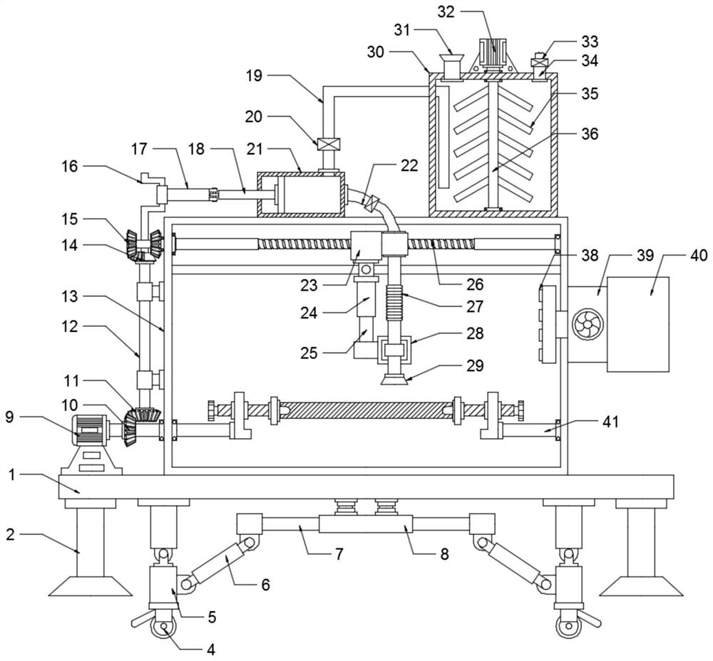
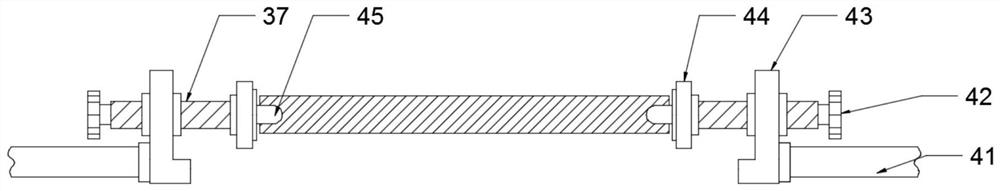
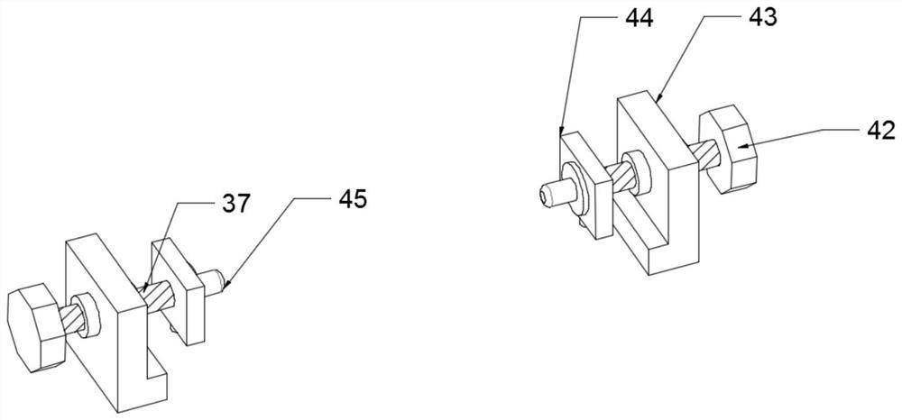
[0021] see Figure 1-3 , a steel pipe spraying device for construction engineering, comprising a support base 1 and a spray box 13, the spray box 13 is installed on the upper surface of the support base 1, the spray box 13 is fixedly connected to the support base 1 by welding, the The left side of the spraying box 13 is provided with a drive motor one 9, and the drive motor one 9 is fixedly connected with the support base 1, and the left and right sides are symmetrically arranged with bearings 43 in the spraying box 13, and the left and right sides are far away from each other. A rotating shaft 41 is fixedly installed on one side, and the rotating shaft 41 is rotationally connected with the inner wall of the spraying box 13. The end of the output shaft of the driving motor-9 passes through the spraying box 13 and is fixedly connected with the rotating shaft 41. 37, the ends of the fastening screw rods 37 on the left and right sides that are close to each other are fixedly conn...

Embodiment 2

[0028] see figure 1 , on the basis of Embodiment 1, in order to make the nozzle 29 move left and right to repeatedly spray the steel pipe, the driving motor-9 rotates, and the driving motor-9 drives the bevel gear-10 to rotate, and the bevel gear-10 drives the bevel gear The gear two 11, the rotating column 12 and the incomplete bevel gear 14 rotate. The incomplete bevel gear 14 drives the screw rod 26 to perform forward and reverse rotation by meshing with the bevel gear three 15 at the left and right ends. The nut 23 drives the bottom nozzle 29 in the horizontal direction. The direction moves back and forth left and right to realize repeated spraying of steel pipes.

[0029] The working principle of the present invention is: a steel pipe spraying device for construction engineering, inserting the left and right ends of the steel pipe to be sprayed into the positioning column 45, by turning the handle 42, the handle 41 drives the fastening screw 37 to rotate, and the fastenin...


PUM


Abstract

The invention discloses a steel pipe spraying device for construction engineering construction, and relates to the technical field of construction engineering equipment. The steel pipe spraying devicecomprises a supporting base and a spraying box. A driving motor I is arranged on the left side of the spraying box. Supports are symmetrically arranged on the left side and the right side in the spraying box and are connected with rotating shafts. Fastening lead screws are arranged within the supports and are connected with clamping plates. Positioning columns are arranged on the surfaces of theclamping plates. The driving motor I is connected with a bevel gear I. A rotating column is arranged on the left side of the spraying box. Two ends of the rotating column are connected with a bevel gear II and an incomplete bevel gear. A screw is arranged above the spraying box. A spraying liquid box is arranged on the right side of the upper surface of the top wall of the spraying box, and is connected with a piston cylinder through a liquid conveying pipe. The rotating shafts drive the supports and a steel pipe to rotate to enable the surface of the steel pipe to be sufficiently and effectively sprayed. The liquid conveying pipe pumps spraying liquid in the spraying liquid box out and conveys the spraying liquid to a spraying pipe and a nozzle, a nut drives the nozzle at the bottom to move left and right in the horizontal direction to realize repeated spraying of the steel pipe.

Description

technical field [0001] The invention relates to the technical field of construction engineering equipment, in particular to a steel pipe spraying device for construction engineering. Background technique [0002] Steel pipe is a kind of steel with a hollow section whose length is much longer than the diameter or circumference. It can be divided into circular, square, rectangular and special-shaped steel pipes according to the cross-sectional shape, and can be divided into carbon structural steel pipes, alloy steel pipes and composite steel pipes according to the material. According to the purpose, it is divided into steel pipes for pipelines, engineering structures, machinery manufacturing, geological drilling, and high-pressure equipment. [0003] Construction steel pipes need to be painted during the production and processing process to improve the service life and appreciation of the steel pipes. When the steel pipes are sprayed, usually one side is sprayed, and then the ...

Claims


Application Information

Patent Timeline
Patent Type & Authority Applications(China)
IPC IPC(8): B05B9/047B05B13/04
CPCB05B9/047B05B13/0442
Inventor 杨庆美
Owner 杨庆美
Why Eureka
Try Eureka