Led illumination source/display with individual led brightness monitoring capability and calibration method

a technology of led illumination source and led brightness, applied in the field of led illumination source/display, can solve the problems of reducing the negative effect of initial quality, affecting the growth potential of such displays, and not being able to display a larger series of ideas

Inactive Publication Date: 2006-10-12
VISIONEERED IMAGE SYST
View PDF15 Cites 281 Cited by
  • Summary
  • Abstract
  • Description
  • Claims
  • Application Information

AI Technical Summary

Benefits of technology

[0024] An objective of the present invention is to provide a means for an LED display to detect and compensate for expected degradation of the LEDs' light output over the life of the display. It is a further object to provide an integral photodetector in close proximity with one or more LEDs to enable the light output from each LED(s) at any time during its life to be measured. It is another object to produce and maintain a quality image on an LED display composed of a multitude of pixels by controlling the absolute output luminance of every LED representative of each discrete color in each pixel so that the display appears uniform in brightness and color across the entire display.

Problems solved by technology

Due to the fixed print nature of this medium, it does not lend itself to displaying a larger series of ideas as would be common with a medium such as television.
Phosphor and incandescent emissive based display technologies have to a limited extent achieved success in displaying varying images in large outdoor and indoor displays.
The current economics and price / performance of traditional LED video and graphic displays is sufficient to replace incandescent, CRT and protection display technology in the existing high value markets, however, the traditional LED displays themselves have drawbacks that impair the growth potential of such displays.
Sorting the individual LEDs into smaller distributions of brightness and hue-bounded ranges, reduces the negative effect on initial quality only.
The long term effect of LED degradation results from LED accumulated operational time and is accelerated by increases in operating junction current, temperature and humidity.
In addition, such advertising is dominated by static image content that results in an increased operational time over the video intensive content of sporting events.
While this solution provides for exceptional image quality of a new display, the long-term prognosis leaves much to be desired outside the intermittent operation during sporting events.
While this method may be suitable for displays concentrated in locations such as Las Vegas, Times Square, and the Los Angeles Sunset Strip, it is not feasible to maintain the calibration of the image quality of thousands of electronic billboards that would be fielded by the billboard operators in the United States.
Notwithstanding the existence of LED sign and billboard display systems and the specialized prior art use of photodetectors the need discussed above has remained unfulfilled.

Method used


Image

  • Led illumination source/display with individual led brightness monitoring capability and calibration method
  • Led illumination source/display with individual led brightness monitoring capability and calibration method
  • Led illumination source/display with individual led brightness monitoring capability and calibration method

Examples


Embodiment Construction

[0045] Use of an Internal Photodetector to Measure the Emitted and Ambient Light An LED illumination source or display made up of an array of modules with each module comprising individual LED groups or pixels, with each pixel constituting a finite area or smallest increment of the source or display, is described in our co-pending U.S. application Ser. No. 10 / 705,515 (“'515 application”), filed Nov. 16, 2003, entitled Video Display Apparatus and the '605 patent. The contents of the '515 application and the '605 patent are incorporated herein by reference.

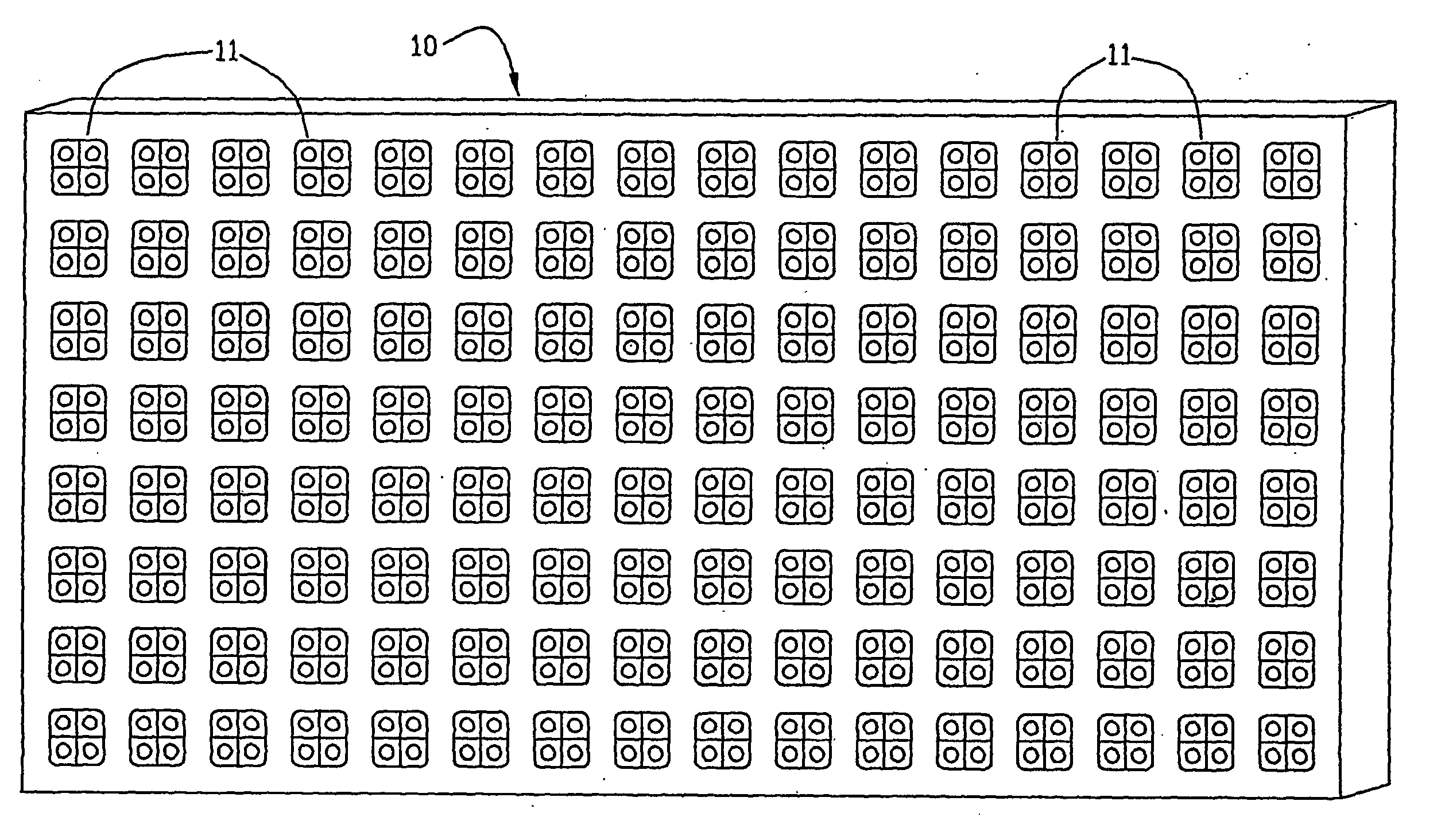
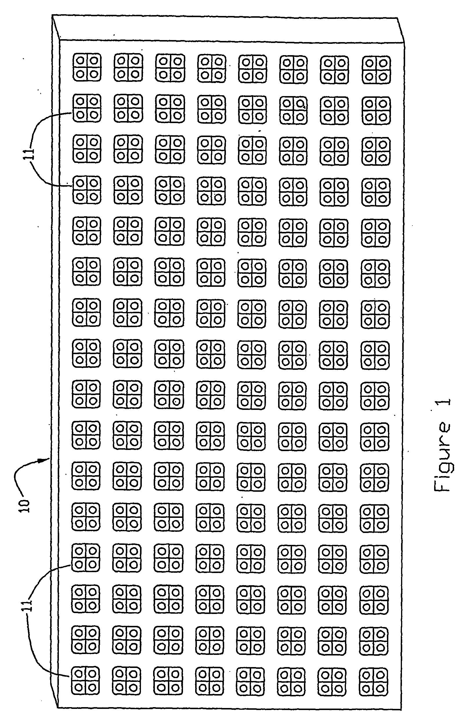
[0046] Referring now to the figures, FIG. 1 illustrates the LED video display module or array 10 as described in the '605 patent in which the array is comprised of individual pixels (picture elements) 11. It is to be understood that a video display is conveniently constructed of individual modules which are assembled in an array to make up the completed sign or billboard. The term “array” as used herein shall mean an individual mod...


PUM


Abstract

An LED area illumination source/display (10) such as an electronic billboard is made up of a number of individual pixels with each pixel including a number of LEDs, e.g., a red (18), blue (19) and green LED (20), with each LED representing a primary color being arranged to be energized separately. At least one light sensor (22) is incorporated into the display for providing a measure of the light emitted from each LED representing a primary color in each pixel. The source/display (10) is susceptible of being self-calibrated by initially energizing the LEDs (18, 19, 20) at less than a maximum level and increasing the energization level as necessary during use to restore the original light output of degraded LEDs.

Description

RELATED APPLICATION [0001] This application is based on U.S. Provisional Application Ser. No. 60 / 465,437, filed Apr. 25, 2003, entitled Self-Calibrating Video Display Apparatus and claims the benefit of the filing date thereof for all common subject matter.FIELD OF THE INVENTION [0002] This invention relates to an LED illumination source / display particularly suitable for large format video and graphic displays in the form of signs and billboards suitable for viewing by a large number of individuals. BACKGROUND OF THE INVENTION [0003] Prior Art Video Displays [0004] Large signs and billboards have been in wide use for many years as a medium for advertising and for imparting information to the public. Traditionally, signs and billboards have been used to exhibit a single advertising theme, product, or message. Due to the fixed print nature of this medium, it does not lend itself to displaying a larger series of ideas as would be common with a medium such as television. Phosphor and in...

Claims


Application Information

Patent Timeline
Patent Type & Authority Applications(United States)
IPC IPC(8): G09G3/32G09G3/20
CPCG09G3/006G09G3/2014G09G3/32G09G2320/0285G09G2320/029G09G2320/043G01J3/506G09G2320/0693G09G2330/12G09G2360/144G09G2360/147G09G2360/148H04N17/04G09G2320/0666G01J1/46G01J2001/4252G09G3/20
Inventor BOLDT, NORTON K. JR.DECKERT, CURTJOHNSON, JAMES C.LISIECKI, ANDREW I.
Owner VISIONEERED IMAGE SYST
Why Eureka
Try Eureka