Electret-based accelerometer

a technology of accelerometer and electro-resonant sensor, which is applied in the direction of magnetic body, magnetic device details, semiconductor/solid-state device device details, etc., can solve the problems of noisy accelerometer signals of electro-resonant accelerometers, and relatively expensive accelerometers to produce compared to other sensors

Active Publication Date: 2006-10-12
MICROSOFT TECH LICENSING LLC
View PDF5 Cites 71 Cited by
  • Summary
  • Abstract
  • Description
  • Claims
  • Application Information

AI Technical Summary

Problems solved by technology

Under the prior art, electret accelerometers have been prone to producing noisy accelerometer signals especially in acoustically

Method used


Image

  • Electret-based accelerometer
  • Electret-based accelerometer
  • Electret-based accelerometer

Examples


Embodiment Construction

[0036] The present invention provides a low-cost accelerometer that is formed by modifying an electret microphone. Electret microphones have been the focus of a significant amount of engineering in an effort to reduce the costs of producing them. This considerable effort has reduced the price point for electret microphones. Accelerometers, on the other hand, continue to be relatively expensive compared to electret microphones.

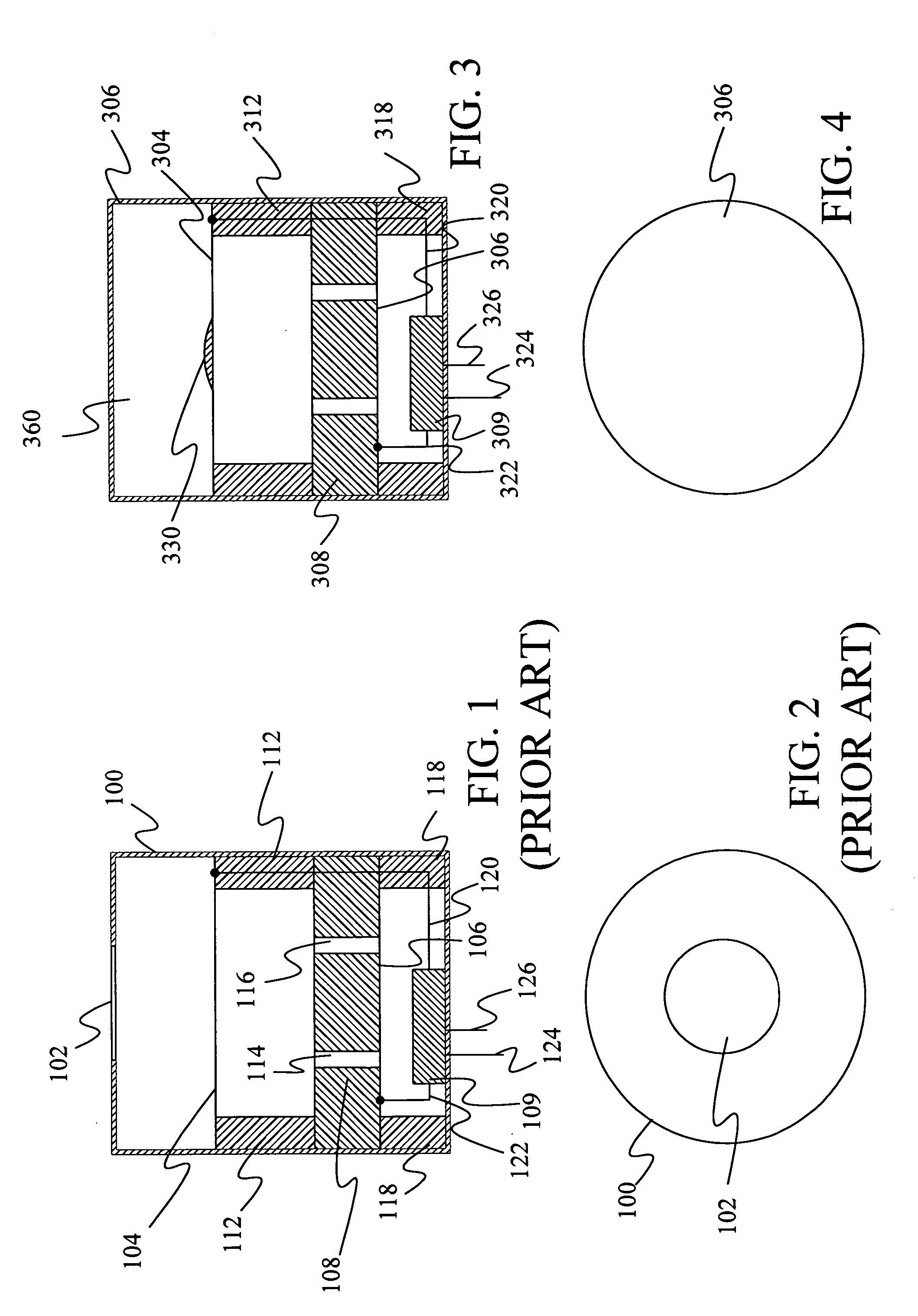
[0037]FIG. 1 provides a cross section of a prior art electret microphone. The microphone includes a casing 100 that has an opening 102. FIG. 2 provides a top view of the electret microphone showing opening 102 in casing 100. In typical electret microphones, casing 100 is around 6 mm in diameter and 5 mm high.

[0038] Within casing 100, the outer periphery of a metalized diaphragm 104 is attached to a spacer 112 such that the center of diaphragm 104 can move relative to the periphery. Metalized diaphragm 104 is designed to have a weight-to-flexibility ratio such...


PUM

PropertyMeasurementUnit
Massaaaaaaaaaa
Flexibilityaaaaaaaaaa
Ratioaaaaaaaaaa

Abstract

An electret accelerometer is provided in which a diaphragm, an electret, a back plate and an electronic circuit are placed in a closed casing.

Description

REFERENCE TO RELATED APPLICATIONS [0001] This application claims the priority benefit of U.S. provisional application 60 / 669,754 filed on Apr. 8, 2005 and entitled ELECTRET-BASED ACCELEROMETER.BACKGROUND OF THE INVENTION [0002] The present invention relates to accelerometers. In particular, the present invention relates to electret-based accelerometers. [0003] An accelerometer is a sensor that provides an electrical signal that is indicative of the acceleration experienced by the sensor. Examples of accelerometers include potentiometric, capacitive, inductive, optical and piezoelectric. [0004] A capacitive accelerometer measures acceleration based on a change in the capacitance of some element in the sensor. One type of capacitive accelerometer is known as an electret-based accelerometers. [0005] An electret-based accelerometer contains an electret, which is a permanently charged material that is an analogue to a permanent magnet. This permanently charged material is placed between ...

Claims


Application Information

Patent Timeline
IPC IPC(8): H04R25/00
CPCG01P15/125H04M1/04H04R19/016Y10T29/4908H04R2499/11Y10T29/49002Y10T29/49005H04R2460/13
Inventor SINCLAIR, MICHAEL J.
Owner MICROSOFT TECH LICENSING LLC
Why Eureka
Try Eureka