Method and apparatus for attenuating error in dynamic and steady-state processes for prediction, control, and optimization
Inactive Publication Date: 2006-10-12
ROCKWELL AUTOMATION TECH
View PDF51 Cites 8 Cited by
Summary
Abstract
Description
Claims
Application Information
AI Technical Summary
This helps you quickly interpret patents by identifying the three key elements:
Problems solved by technology
Method used
Benefits of technology
Benefits of technology
[0007] The present invention disclosed and claimed herein comprises a method and apparatus for controlling the operation of a plant by predicting a change in the dynamic input values to the plant to effect a change in the output from a current output value at a first time to a desired output value at a second time. The controller includes a dynamic predictive model fore receiving the current input value and the desired output value and predicting a plurality of input values at different time positions between the first ti
Problems solved by technology
These measurements do not account for the perturbations that exist when changing from one steady-state condition to another steady-state condition.
Unfortunately, almost always the dynamic gain k does not equal the steady-state gain K, since the steady-state gain is modeled on a much larger set of data, whereas the dynamic gain is defined around a set of operating conditions wherein an existing set of operating conditions are mildly perturbed.
This results in a shortage of sufficient non-linear information in the dynamic data set in which non-linear information is contained within the stati
Method used
Image
Click on the blue label to locate the original text in one second.
Reading with bidirectional positioning of images and text.
Examples
Embodiment Construction
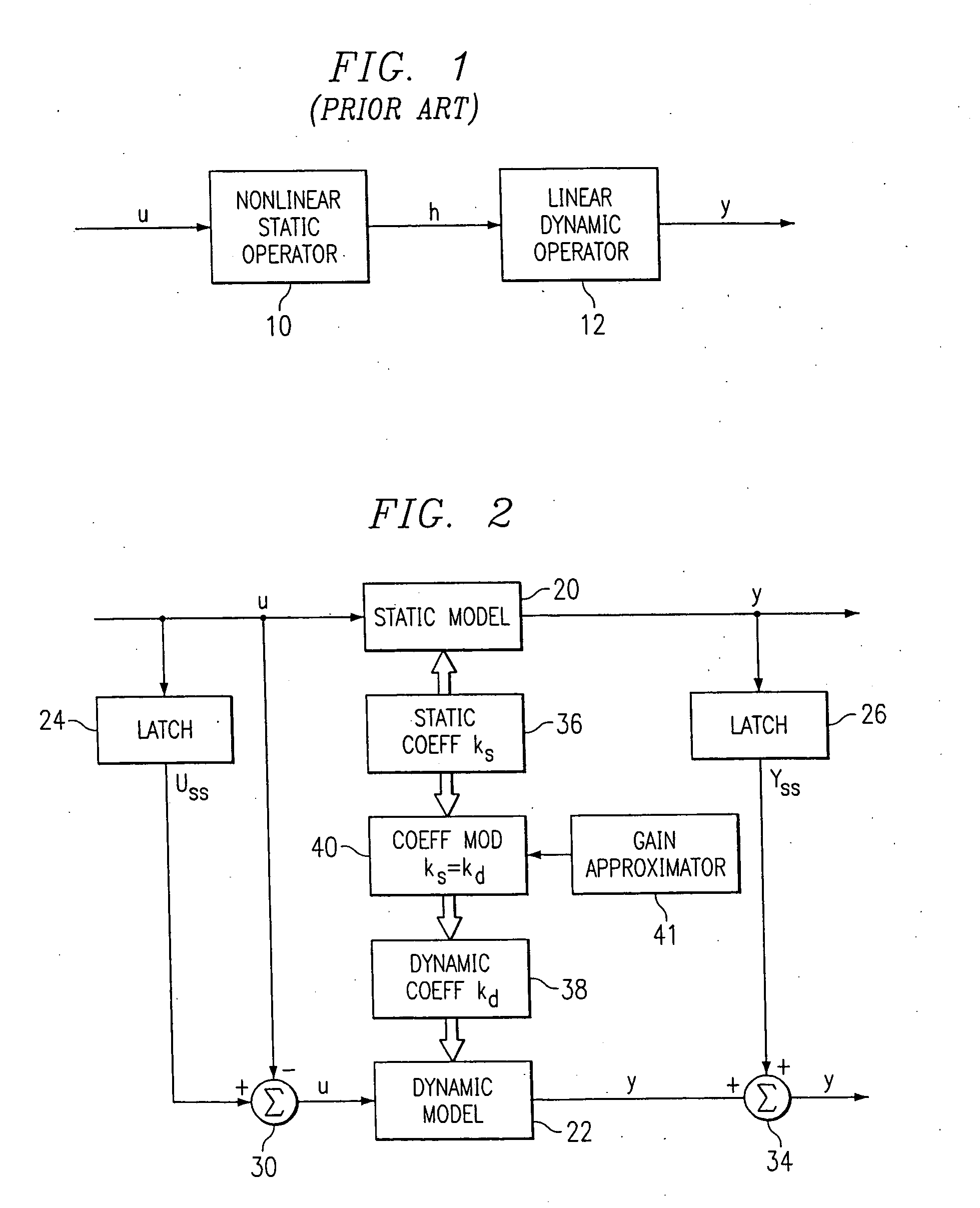
[0039] Referring now to FIG. 1, there is illustrated a diagrammatic view of a Hammerstein model of the prior art. This is comprised of a non-linear static operator model 10 and a linear dynamic model 12, both disposed in a series configuration. The operation of this model is described in H. T. Su, and T. J. McAvoy, “Integration of Multilayer Perceptron Networks and Linear Dynamic Models: A Hammerstein Modeling Approach” to appear in I & EC Fundamentals, paper dated Jul. 7, 1992, which reference is incorporated herein by reference. Hammerstein models in general have been utilized in modeling non-linear systems for some time. The structure of the Hammerstein model illustrated in FIG. 1 utilizes the non-linear static operator model 10 to transform the input U into intermediate variables H. The non-linear operator is usually represented by a finite polynomial expansion. However, this could utilize a neural network or any type of compatible modeling system. The linear dynamic operator mo...
PUM
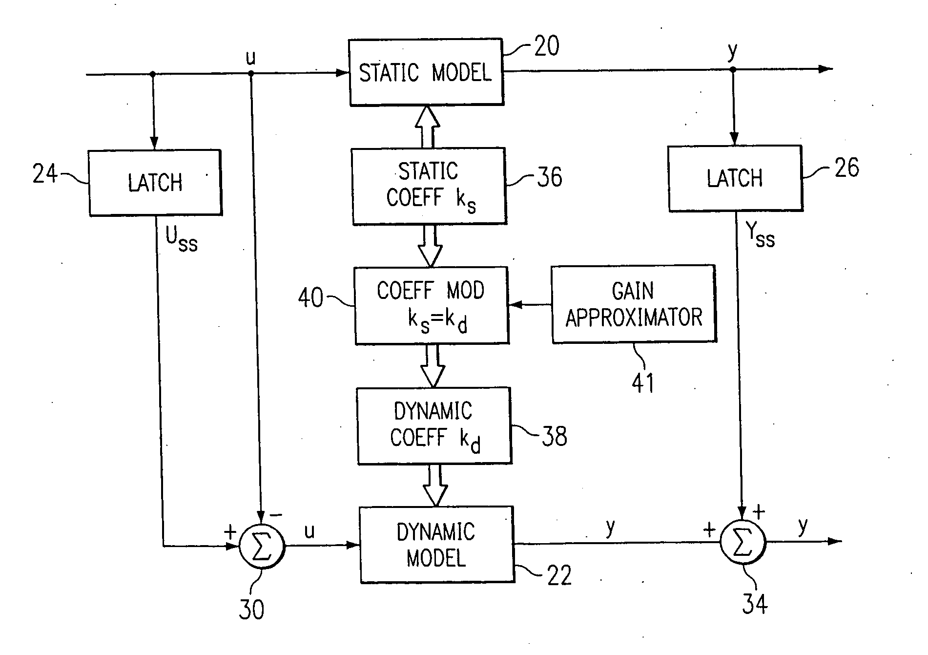
Abstract
A method for providing independent static and dynamic models in a 000 prediction, control and optimization environment utilizes an independent static model (20) and an independent dynamic model (22). The static model (20) is a rigorous predictive model that is trained over a wide range of data, whereas the dynamic model (22) is trained over a narrow range of data. The gain K of the static model (20) is utilized to scale the gain k of the dynamic model (22). The forced dynamic portion of the model (22) referred to as the bi variables are scaled by the ratio of the gains K and k. The bi have a direct effect on the gain of a dynamic model (22). This is facilitated by a coefficient modification block (40). Thereafter, the difference between the new value input to the static model (20) and the prior steady-state value is utilized as an input to the dynamic model (22). The predicted dynamic output is then summed with the previous steady-state value to provide a predicted value Y. Additionally, the path that is traversed between steady-state value changes.
Description
CROSS-REFERENCE TO RELATED APPLICATIONS [0001] This application is a Continuation in Part of U.S. patent application Ser. No. 10 / 847,211, filed May 17, 2004, entitled “Dynamic Controller for Controlling a System”, which is a Continuation of U.S. patent application Ser. No. 10 / 302,923, filed Nov. 22, 2002, entitled “Method and Apparatus for Modeling Dynamic and Steady-State Processes for Prediction, Control, and Optimization”, which is a ontinuation of U.S. Pat. No. 6,487,459, issued Nov. 26, 2002, entitled “Method and Apparatus for Modeling Dynamic and Steady-State Processes for Prediction, Control, and Optimization”, which is a Continuation of U.S. Pat. No. 5,933,345, issued Aug. 3, 1999, entitled “Method and Apparatus for Dynamic and Steady State Modeling Over a Desired Path Between Two End Points”.TECHNICAL FIELD OF THE INVENTION [0002] The present invention pertains in general to modeling techniques and, more particularly, to combining steady-state and dynamic models for the pur...
Claims
Application Information
Patent Timeline
Application Date:The date an application was filed.
Publication Date:The date a patent or application was officially published.
First Publication Date:The earliest publication date of a patent with the same application number.
Issue Date:Publication date of the patent grant document.
PCT Entry Date:The Entry date of PCT National Phase.
Estimated Expiry Date:The statutory expiry date of a patent right according to the Patent Law, and it is the longest term of protection that the patent right can achieve without the termination of the patent right due to other reasons(Term extension factor has been taken into account ).
Invalid Date:Actual expiry date is based on effective date or publication date of legal transaction data of invalid patent.
IPC IPC(8): G05B13/02
CPCG05B13/027G05B13/048G05B13/042
InventorBOE, EUGENEPICHE, STEPHENMARTIN, GREGORY D.

