Inductor Current Emulator

a current emulator and current technology, applied in the field of switching power supplies, can solve the problems of slow response to line and load variations, relative slow response, and power mode control suffers

Active Publication Date: 2018-06-21
ROHM CO LTD
View PDF3 Cites 2 Cited by
  • Summary
  • Abstract
  • Description
  • Claims
  • Application Information

AI Technical Summary

Benefits of technology

[0017]a second circuit providing an emulated current waveform of current in the inductor, wherein the second circuit employs the inductance value in providing the emulated current waveform and wherein the circuit is responsive to an error value representative of the difference between the waveforms of the first and second waveforms to adjust the inductance value to minimize the error value.

Problems solved by technology

Voltage mode control suffers from a number of disadvantages including, for example, slow response to line and load variations.
This usually means relative slow response.

Method used


Image

  • Inductor Current Emulator
  • Inductor Current Emulator
  • Inductor Current Emulator

Examples


Embodiment Construction

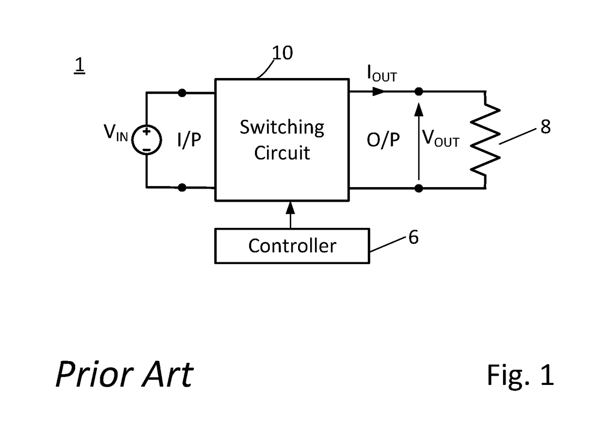
[0040]As explained above, current mode controlled switching power supplies offer several advantages over voltage mode switching power supplies. These advantages include that current mode exhibits fast dynamic response to the load transients and line transients. Additionally, current mode offers higher reliability with fast, cycle-by-cycle current sensing for output short circuit and overload protection. In contrast, voltage mode controlled power supplies are slower to react to an over current condition which can result in a failure in some applications. Current mode control also allows for simple and reliable feedback loop compensation ensuring the controlled power supply is stable with all ceramic output capacitors making for a smaller solution size. Also, the use of current mode control makes accurate current sharing in high current multiphase designs easier.

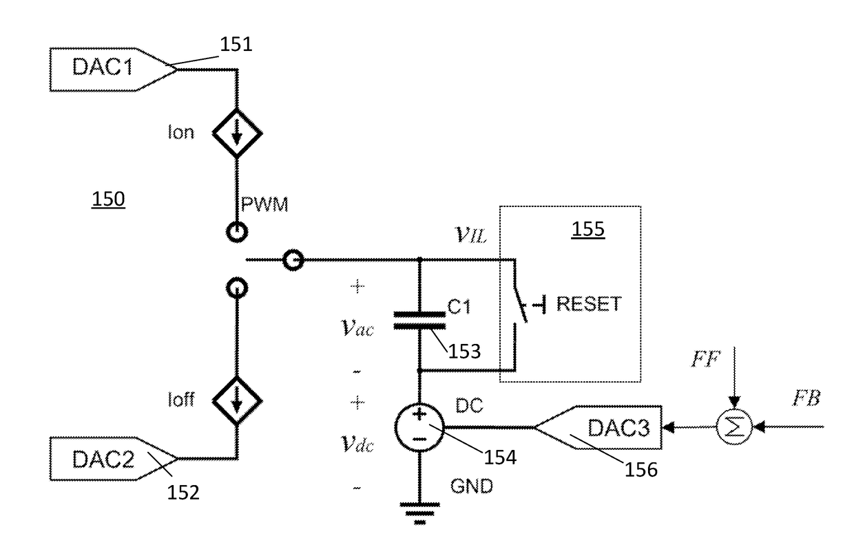
[0041]The present application provides a control arrangement with an improved inductor current emulator which provides digit...


PUM


Abstract

The present application relates to controllers using current mode control to control the operation of switching power supplies such as DC-DC converters. The application provides an inductor current.

Description

RELATED APPLICATIONS[0001]This application claims the benefit of U.S. provisional patent application 62 / 436,155, filed Jun. 19, 2016 and entitled “An Inductor Current Emulator,” the entirety of the disclosure of which is incorporated herein for all purposes.FIELD OF THE APPLICATION[0002]The present application relates to switching power supplies and in particular to a controller for a switching power supply and a method of emulating inductor current in such controllers.BACKGROUND OF THE APPLICATION[0003]The general purpose of a controller in a power supply is to try and ensure that the output voltage of the power supply follows a reference value.[0004]A conventional arrangement employing such a controller is shown generally in FIG. 1.[0005]In the arrangement shown, the power supply circuit has a switching circuit 10 which provides a regulated output voltage VOUT to a load 8 from an input voltage VIN. As would be familiar to those skilled in the art, the switching circuit, also refer...

Claims


Application Information

Patent Timeline
Patent Type & Authority Applications(United States)
IPC IPC(8): H02M3/158H02M3/157
CPCH02M3/157H02M3/156
Inventor HARTMAN, MARKMIAO, BOTAO
Owner ROHM CO LTD
Why Eureka
Try Eureka