Racecourse lap counter and racecourse for radio controlled vehicles

a technology of radio controlled vehicles and lap counters, which is applied in the field of system for compiling and displaying racecourse data, can solve the problems of difficult to achieve the effect of easy change, low cost, and easy for competitors to “cut” corners and cheat the course,

Inactive Publication Date: 2006-10-12
FREIFELD DANIEL
View PDF19 Cites 15 Cited by
  • Summary
  • Abstract
  • Description
  • Claims
  • Application Information

AI Technical Summary

Benefits of technology

[0014] Accordingly, it is an object of the invention to provide a method to monitor and display the speed and position of a vehicle traversing a predefined path. A second object of the invention is for the predefined path to be easily changed.
[0015] Among the features of the invention are that the method for monitoring information regarding the vehicles has a minimum impact, if any, on the operation of the vehicles and the information is readily displayed at a remote location. This feature is achieved through the combination of a sensor and a unique identifier, one of which is located on the vehicle and the other on a gate to be traversed by the vehicle. Either one of the sensor or the unique identifier may be powered and the other passive. Another feature of the invention is that it is particularly suited for monitoring the speed and relative position of a number of racing radio controlled vehicles traveling along a predefined racecourse and displaying information regarding speed and ranking on a remote scoreboard.
[0016] Advantages of this invention include creation a race circuit for R / C cars easily and inexpensively both indoors and outdoors on surfaces, including but not limited to, asphalt or dirt. Another advantage of this invention is that it provides a relatively inexpensive lap counter to track and display the position and race times of the R / C cars in the race. Another advantage of this invention is that it minimizes the amount of weight that must be carried by a car for an identifying mark.

Problems solved by technology

While racecourse radio controlled (R / C) cars and other racing vehicles such as R / C boats, trucks and motorcycles have been a consistently popular over the years, a simple, inexpensive, way to define a racecourse and to count laps of a race has not been readily available.
Simple approaches, such as placing cones or drawing the course with chalk on asphalt have as one obvious disadvantage that it is easy for a competitor to “cut” a corner and cheat the course.
Constructing such racecourses are time consuming and requires significant effort and expense.
Further, such courses are not readily portable.
While many devices are currently available they can be expensive.
This method is expensive utilizing relatively costly transmitting and receiving radio electronics.
The computer program tracks the race and displays the lap results and times. The electronics module to receive and process these faint signals is expensive and time consuming to build.
Once again the receive optics and electronics for this device is costly.
The structure to suspend these LEDs is relatively large and costly.
Due to the fixturing of the markers and second transmitters, this system is not amenable to rapid reconfiguration of the racecourse and may lead to driver boredom after a number of runs around the same predefined path.
Also, the second transmitter adds expense to the entire system.

Method used


Image

  • Racecourse lap counter and racecourse for radio controlled vehicles
  • Racecourse lap counter and racecourse for radio controlled vehicles
  • Racecourse lap counter and racecourse for radio controlled vehicles

Examples


Embodiment Construction

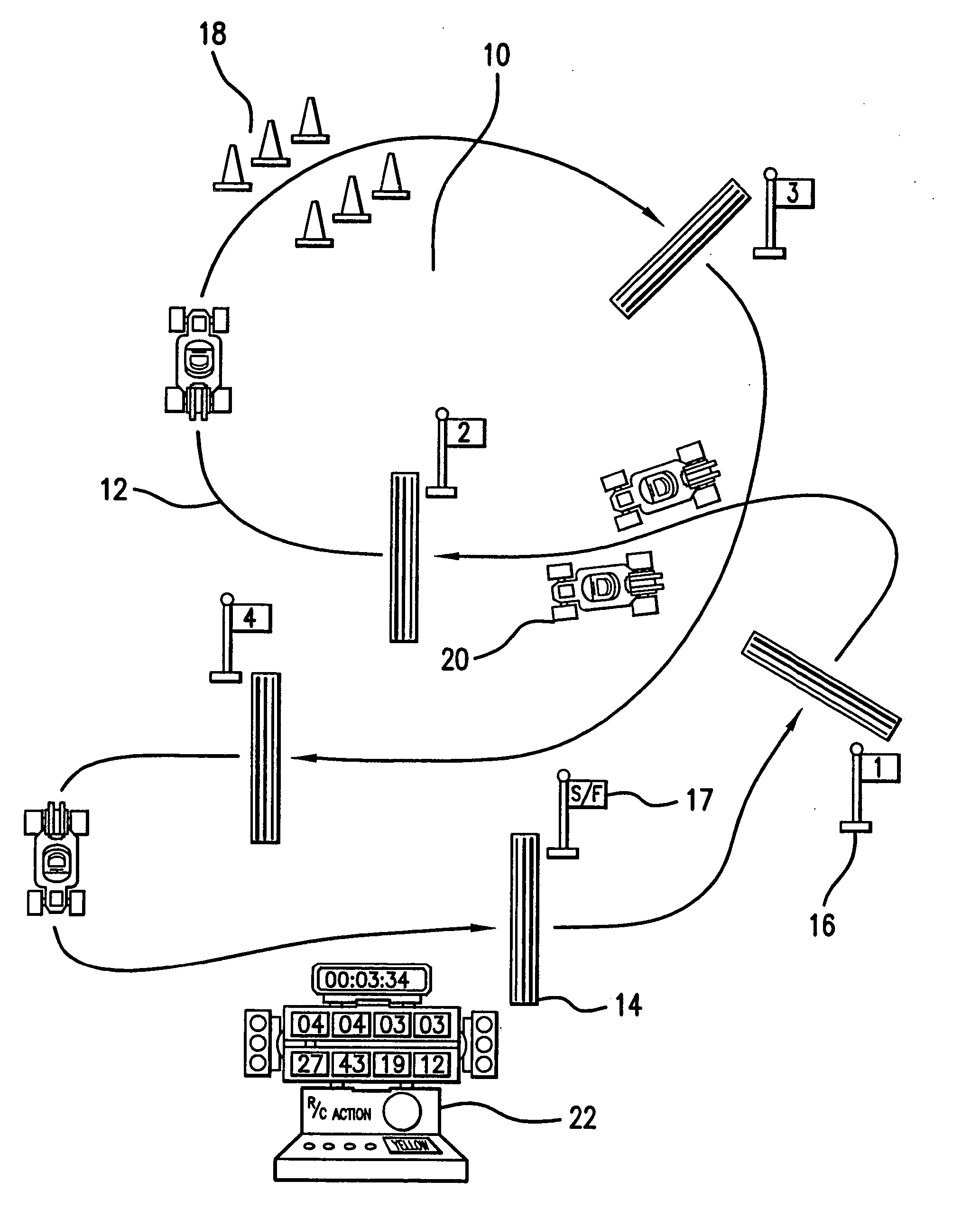
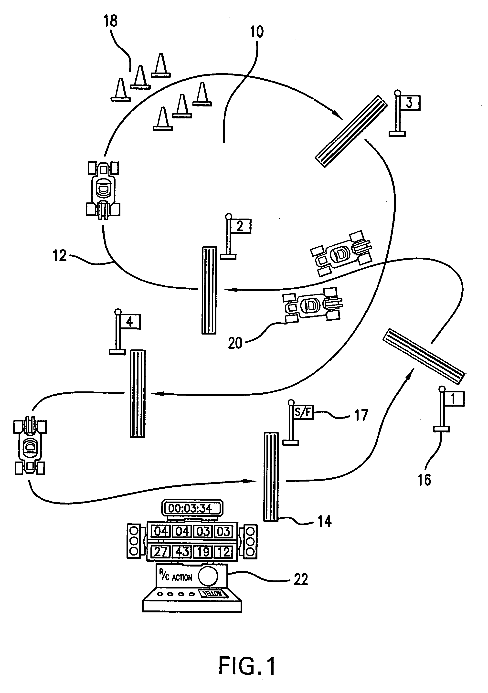
[0032] In accordance with the invention, there is a combination of a racecourse and a plurality of racing vehicles. With reference to FIG. 1, the racecourse 10 has a predefined path 12 that is defined by at least one marker or gate 14. Unlike prior art racecourses requiring permanent fixturing to define the path, the present path is defined by gates 14, that are preferably easily moved as described below. The order the vehicles must negotiate the course is given by a number marker 16. The predefined path 12 is thus defined by this order. One lap of the course is completed when all the gates have been crossed by a vehicle in the proper order, preferably terminating at a start / finish gate 17.

[0033] While the traditional wood or plastic walls to define the course are no longer needed, to add visual interest to the race, borders 18 of the race circuit may be formed by any convenient method. One simple method is lines of chalk drawn in the form of a track on asphalt or another hard surf...


PUM


Abstract

A combination of a racecourse and a plurality of racing vehicles where the racecourse has a predefined path defined by at least one gate. This gate further includes a unique identifier. Each of the plurality of racing vehicles has a sensor capable of detecting the unique identifier and the sensor is further coupled to a logic circuit and to a transmitter. A scoreboard has receiver to receive information from the transmitter and display that information, such as lap speed and ranking, according to a desired format. Alternatively, the unique identifier is mounted to the racing vehicle and the sensor to the gate.

Description

CROSS REFERENCE TO RELATED PATENT APPLICATIONS [0001] This patent application is a divisional application of U.S. patent application Ser. No. 10 / 746,597 filed on Dec. 23, 2003, which claims priority of U.S. Provisional Patent Application Ser. No. 60 / 436,351 that was filed on Dec. 24, 2002. The disclosures of both documents are incorporated by reference in their entireties herein.BACKGROUND OF THE INVENTION [0002] 1. Field of the Invention [0003] This patent application relates to systems for compiling and displaying racecourse data. More particularly, this invention relates to method to define a racecourse along a predefined path. As race vehicles traverse this path, information regarding the race vehicles, such as speed and ranking, is communicated to a scoreboard for display. [0004] 2. Description of Related Art [0005] While racecourse radio controlled (R / C) cars and other racing vehicles such as R / C boats, trucks and motorcycles have been a consistently popular over the years, a ...

Claims


Application Information

Patent Timeline
Patent Type & Authority Applications(United States)
IPC IPC(8): G04F10/00G04F5/00A63H18/02
CPCA63H18/005G07C1/24A63H18/026
Inventor FREIFELD, DANIEL
Owner FREIFELD DANIEL
Why Eureka
Try Eureka