High-strength, lightweight blow-molded plastic structures

Inactive Publication Date: 2006-10-19
LIFETIME PRODUCTS
View PDF4 Cites 102 Cited by
  • Summary
  • Abstract
  • Description
  • Claims
  • Application Information

AI Technical Summary

Benefits of technology

[0011] A need therefore exists for structures constructed from blow-molded plastic tha

Problems solved by technology

Because blow-molded structures include a hollow interior space, many blow-molded structures are not high-strength.
In fact, many known blow-molded structures are relatively low-strength and are unable to support a relatively large amount of weight or force.
Disadvantageously, the metal ribs must be attached to the table top by mechanical fasteners such as bolts or screws.
The bolts or screws require holes in the table top, which may create stress concentrations and/or potential failure points in the table top.
Alternatively, the metal ribs may be attached to the table top by adhesives, but the adhesives may also decrease the structural integrity of the table top and make the table top very difficult to repair or replace.
In addition, the metal ribs may increase the number of components required to construct the table and the time required to manufacture the table.
Thus, while it is known to use metal ribs to increase the strength of a blow-molded table top, the metal ribs may undesirably increase the time and costs to manufacture the table.
Further, the attachment of the metal ribs to the table top may decrease the strength and/or structural integrity of the table top, and increase the potential causes of failure of the table.
Disadvantageously, the thicker outer walls of the ribs may requ

Method used


Image

  • High-strength, lightweight blow-molded plastic structures
  • High-strength, lightweight blow-molded plastic structures
  • High-strength, lightweight blow-molded plastic structures

Examples


Embodiment Construction

[0011] A need therefore exists for structures constructed from blow-molded plastic that eliminates or reduces some or all of the above-described disadvantages and problems.

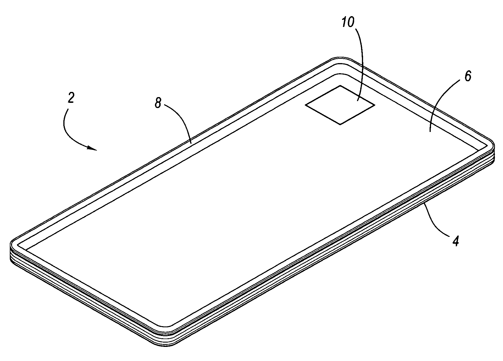
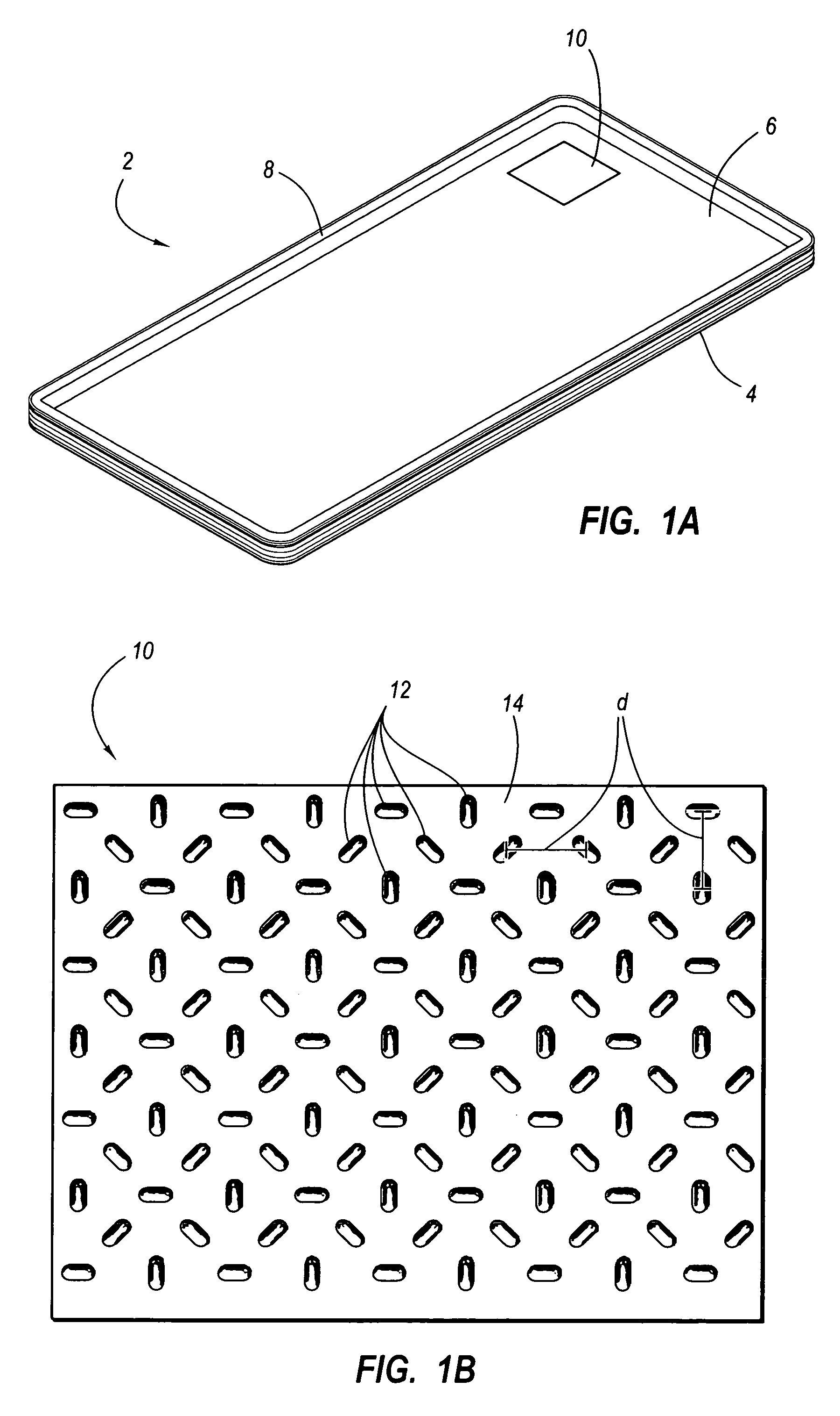
[0012] One aspect is a structure that can be constructed from blow-molded plastic and have increased strength. Preferably the blow-molded plastic structure has both increased strength and it is lightweight, but the structure does not have to be lightweight and high-strength.

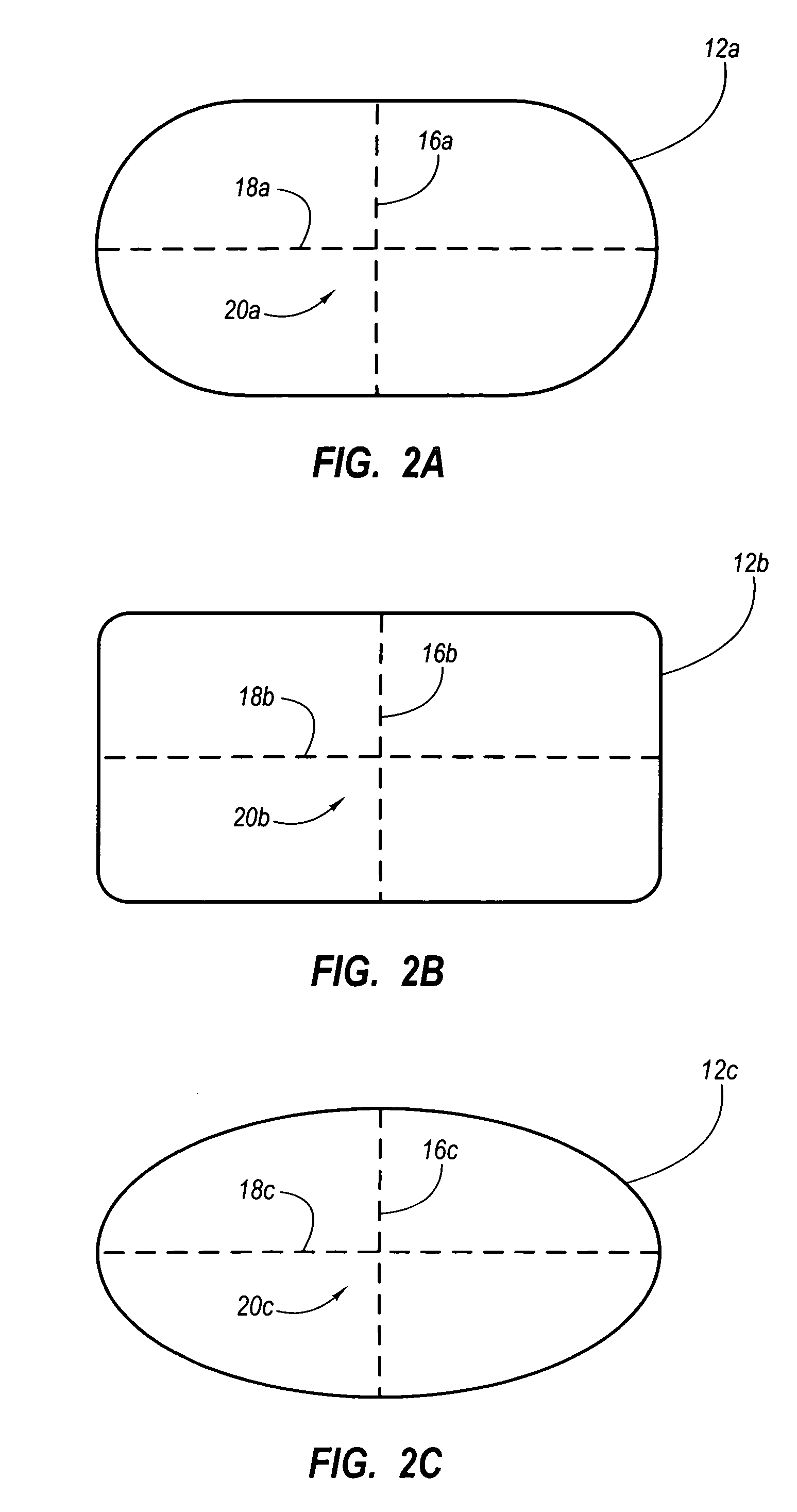
[0013] Another aspect is a structure that can be constructed from blow-molded plastic and include opposing surfaces. The opposing surfaces may be separated by a generally constant or other predetermined distances. For example, the opposing surfaces may include one surface that is generally planar and the other surface may include a plurality of depressions that are sized and configured to increase the strength of the blow-molded structure. The depressions may cover only a portion of the surface, substantially all of the surface, or the entire...


PUM

PropertyMeasurementUnit
Angleaaaaaaaaaa
Angleaaaaaaaaaa
Angleaaaaaaaaaa

Abstract

Blow-molded plastic structures may include a plurality of depressions and the depressions may have different characteristics depending, for example, upon the particular configuration of the depression. For example, a depression may have an elongated length and it may have increased strength along its length. The depressions may be arranged into a pattern in order to take advantage of particular characteristics of the depressions. For example, the depressions may be arranged to maximize the strength and/or minimize the weight of the structure. The depressions may also be arranged to create a structure with generally uniform characteristics. Significantly, the depressions may be arranged into a number of different patterns depending, for example, upon the intended use of the structure. For instance, the depressions may be arranged into a pattern with one or more rows and columns, and the depressions may be disposed in particular positions or orientations within the rows or columns.

Description

CROSS-REFERENCE TO RELATED APPLICATIONS [0001] This application claims priority to, and the benefit of, U.S. provisional patent application Ser. No. 60 / 659,982, filed Mar. 9, 2005, which is incorporated by reference.BACKGROUND OF THE INVENTION [0002] 1. Field of the Invention [0003] The present invention generally relates to structures constructed from blow-molded plastic and, in particular, to high-strength, lightweight blow-molded plastic structures. [0004] 2. Description of Related Art [0005] It is known to construct various objects and items, such as tables, chairs, partitions, walls, and sports equipment, from plastic. It is also known to construct some of these and other objects from blow-molded plastic. As known to those skilled in the art, blow-molded structures often include an outer wall that encloses a hollow interior space. Because blow-molded structures include a hollow interior space, many blow-molded structures are not high-strength. In fact, many known blow-molded st...

Claims


Application Information

Patent Timeline
IPC IPC(8): B65D19/00
CPCA47B13/08B29C49/00B65D71/70B29L2031/448B65D11/24B29C49/52
Inventor HANEY, THAYNE B.HOWE, RICH
Owner LIFETIME PRODUCTS
Why Eureka
Try Eureka