Engine oil supply apparatus
a technology for engine oil supply and oil pump, which is applied in the direction of pressure lubrication, pressure lubrication, lubrication elements, etc., can solve the problems of unsatisfactory second oil pump size and unsatisfactory smooth movement for a long time, and achieve the effect of improving control respons
- Summary
- Abstract
- Description
- Claims
- Application Information
AI Technical Summary
Benefits of technology
Problems solved by technology
Method used
Image
Examples
first embodiment
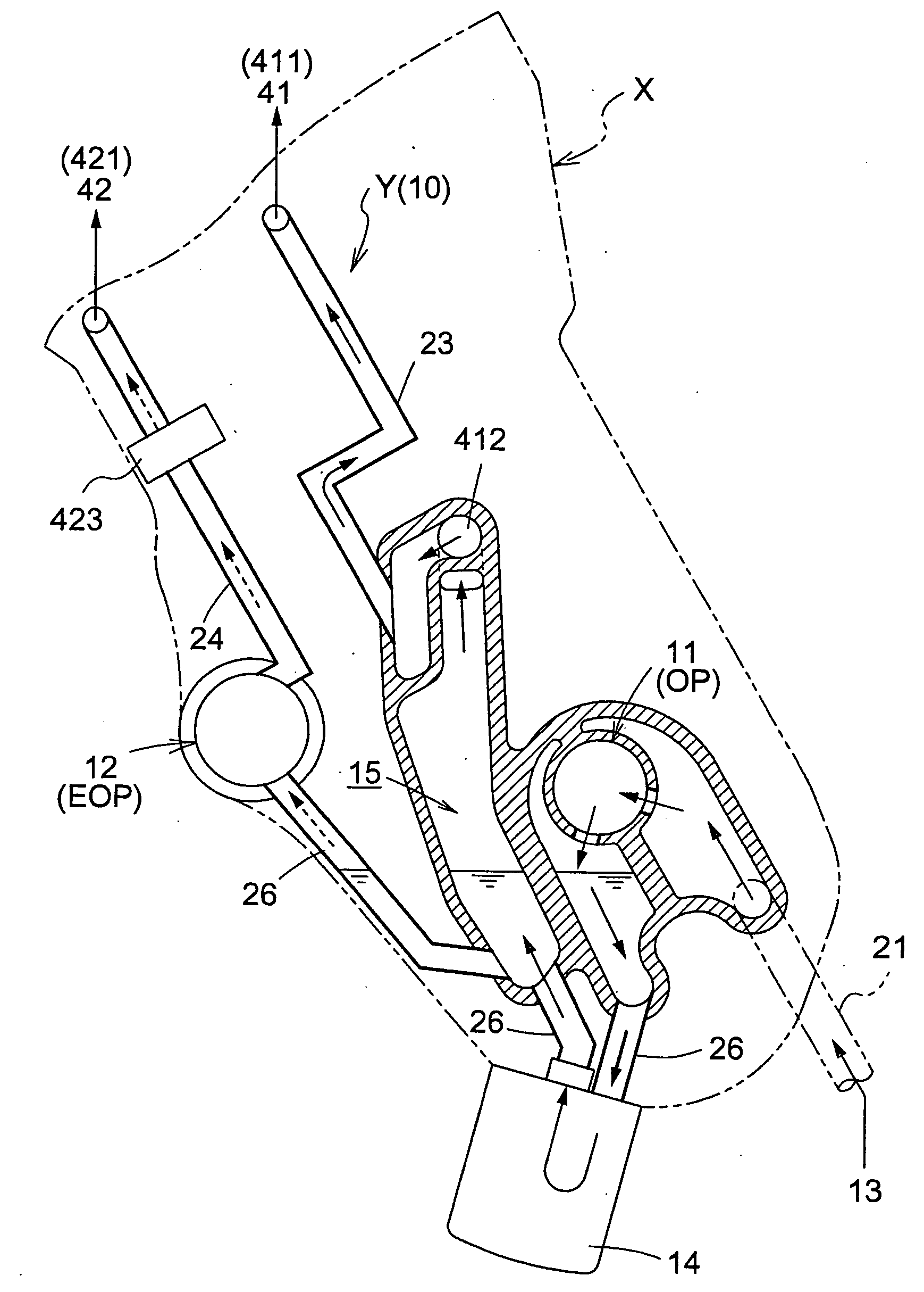
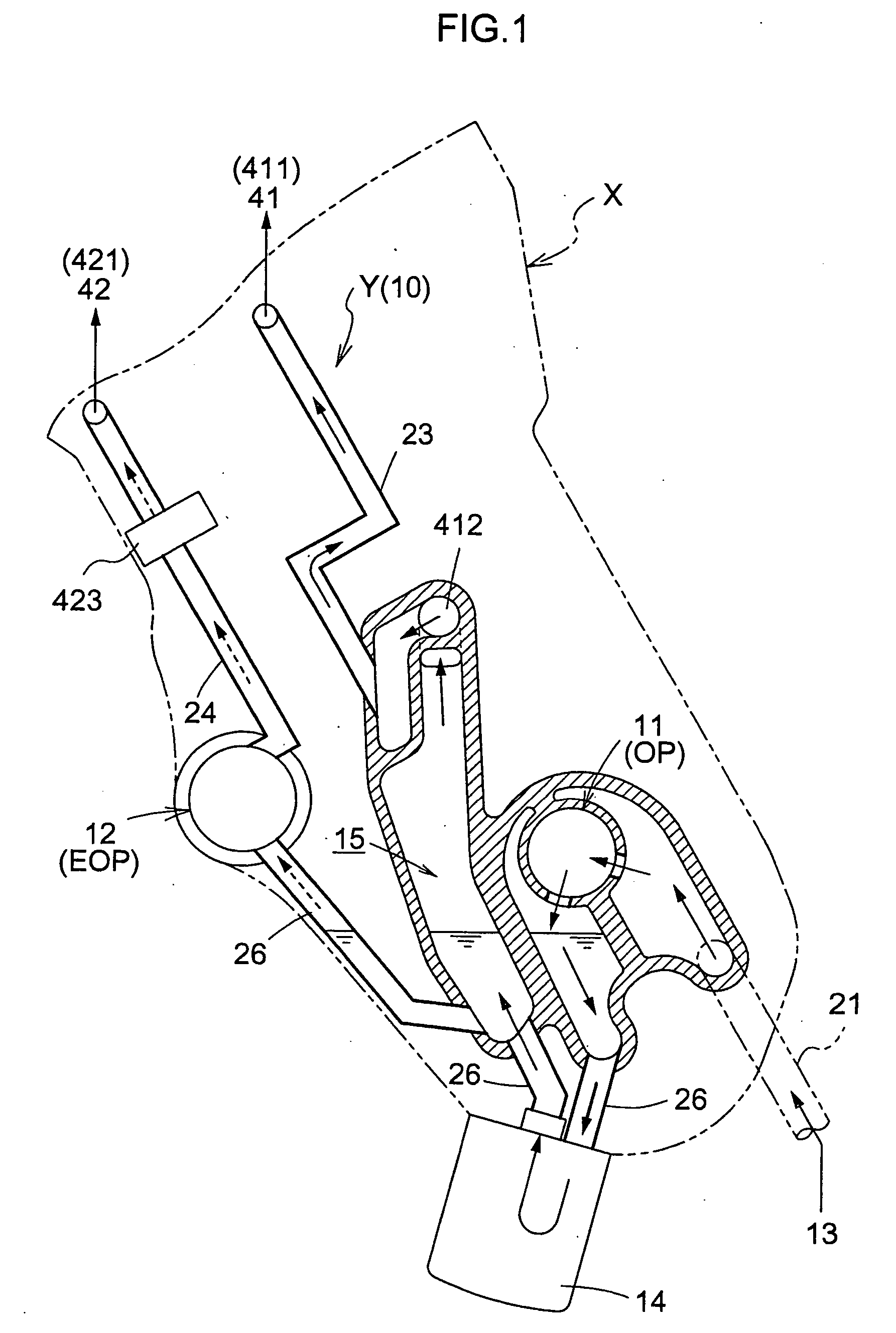
[0064]FIG. 1 schematically shows an oil supply apparatus Y of the present invention viewed from a side of an engine X. FIG. 5 schematically shows oil supply paths in a control hydraulic circuit 10 of the oil supply apparatus Y.
[0065] The control hydraulic circuit 10 includes, for example, oil pumps for supplying oil to any portion in an engine requiring lubrication, oil passages for circulating the oil, valves for controlling the circulation of the oil, etc. An oil holder 13 holds the oil.
[0066] In the present invention, the oil pumps are a first oil pump 11 driven in synchronism with a crankshaft and a second oil pump 12 connected in series with the first oil pump 11 and driven independently of the first oil pump 11. These oil pumps may be, for example, mechanical oil pumps or electrically driven oil pumps.
[0067] Hereunder, a mechanical oil pump (OP) is used as the first oil pump 11 and an electrically driven oil pump (EOP) is used as the second oil pump 12.
[0068] The first oil...
second embodiment
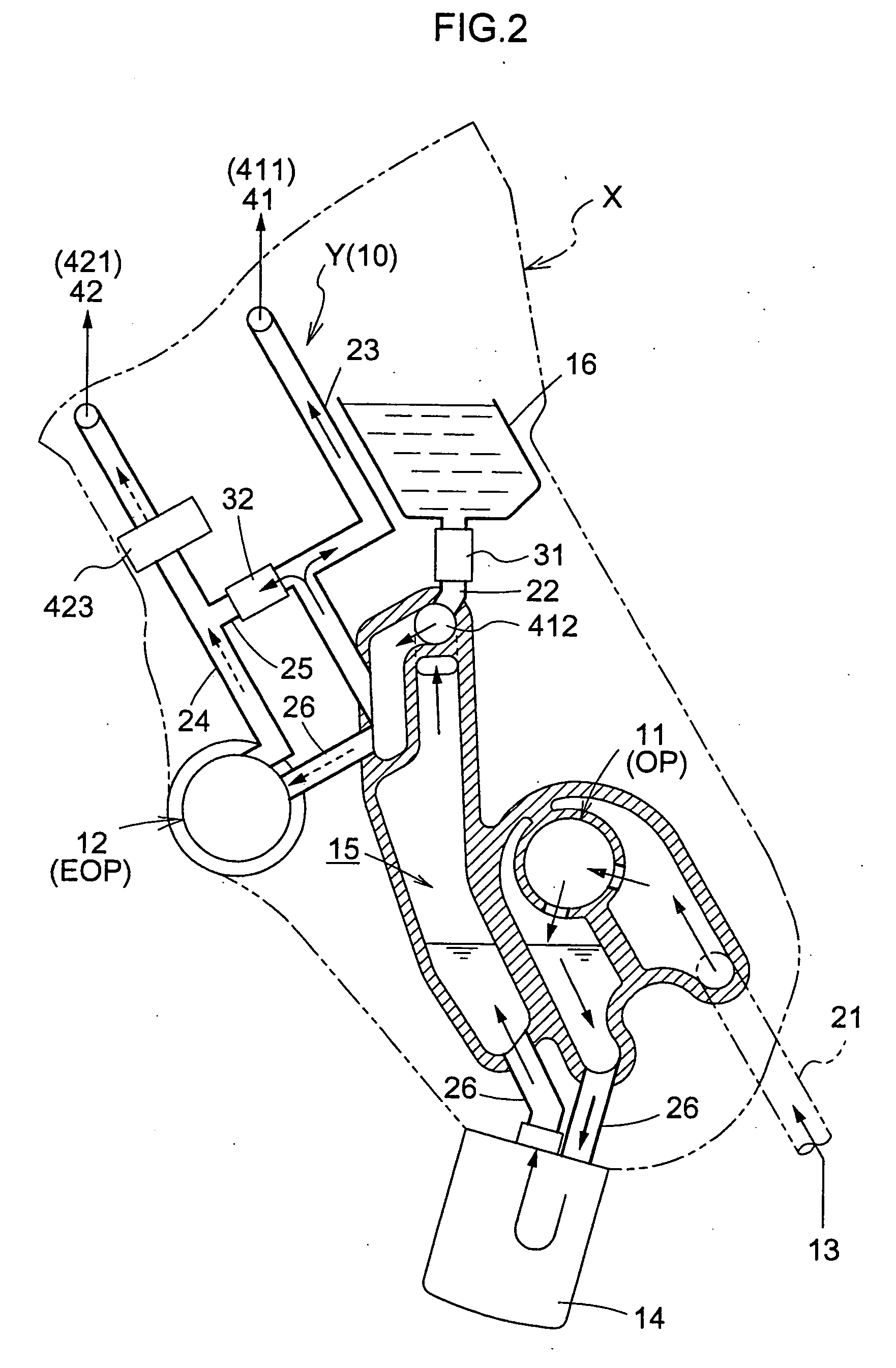
[0081] In the present invention, as shown in FIGS. 2 and 6, a second oil reservoir 16 may be disposed independently of the first oil reservoir 15.
[0082] In this case, the second oil reservoir 16 can be disposed at a height that is higher than that at which the oil holder 13 is disposed. For example, oil is supplied to the second oil pump 12 from the second oil reservoir 16 through a second oil passage 22, communicating with the main gallery 412 from the second oil pump 16, and through the connection oil passage 26 connected to the second oil pump 12.
[0083] The location where the second oil reservoir 16 is disposed is not particularly limited, so that it may be disposed at any location. Therefore, the engine can be designed with sufficient freedom. In the present embodiment, as described above, the second oil reservoir 16 is disposed at a high position. The oil stored in the second oil reservoir 16 has potential energy with respect to the second oil pump 12. Therefore, for example,...
third embodiment
[0100]FIGS. 3 and 7 show a modification of the first embodiment.
[0101] Here, the second oil reservoir 16 provided specifically for the second oil pump 12 is disposed below the second oil pump 12. The second oil reservoir 16 is formed independently of the oil holder 13. This makes it possible to reliably supply the oil to the second oil pump 12. The oil at the second oil reservoir 16 is supplied through the second oil passage 22 connected to the connection oil passage 26. The first valve 31 is disposed at the second oil passage 22.
[0102] As in the previous embodiment, the first valve 31 is, for example, a check valve. For example, when the engine is started, oil is supplied to the second oil pump 12 through the second oil passage 22 until oil is supplied from the first oil pump 11. When the pressure of the first oil pump 11 is increased, the oil is supplied to the second oil pump 12 by it rather than from the second oil passage 22. Here, the first valve 31 prevents reverse flow of ...
PUM
 Abstract
Description
Claims
Application Information
 - R&D
- Intellectual Property
- Life Sciences
- Materials
- Tech Scout
- Unparalleled Data Quality
- Higher Quality Content
- 60% Fewer Hallucinations
Browse by: Latest US Patents, China's latest patents, Technical Efficacy Thesaurus, Application Domain, Technology Topic, Popular Technical Reports.
© 2025 PatSnap. All rights reserved.Legal|Privacy policy|Modern Slavery Act Transparency Statement|Sitemap|About US| Contact US: help@patsnap.com


