RFID tag and antenna arranging method

a technology of arranging method and rfid tag, which is applied in the direction of burglar alarm mechanical actuation, burglar alarm by hand-held articles removal, etc., can solve the problems of affecting the communication range between the rfid tag and the reader/writer, affecting the communication performance, and affecting the communication range, so as to prevent the interference between the antenna and the antenna, prevent the interference between the antenna

Inactive Publication Date: 2006-10-19
FUJITSU LTD
View PDF3 Cites 82 Cited by
  • Summary
  • Abstract
  • Description
  • Claims
  • Application Information

AI Technical Summary

Benefits of technology

[0021] According to an aspect of the present invention, in the RFID tag, the interference prevention unit coats at least one of the antennas with a material that transmits electromagnetic waves of a frequency band to be transmitted and received by the corresponding antenna, to prevent the interference between the antennas.
[0022] A method of arranging antennas in an RFID tag including a plurality of an

Problems solved by technology

Moreover, passive-type RFID tags do not have built-in batteries because they use the electromagnetic fields or the electric waves transmitted from the reader/writer as a power source of the IC chip.
Therefore, in an environment installed with these devices, communication performance can be largely affected and deteriorated.
Thus, in a moist environment, communication range between the RFID tags and the reader/writer can become unstable.
However, the 13.56 MHz HF band is largely affected by metal objects, which leads to a significant decrease in the communication range or a communication failure.
However, because the UHF band uses electric waves, communication errors can be caused in a moist environment, although the UHF band is not as susceptible to moisture as the microwave band.
Typically, passive-type RFID tags can only accept a single frequency band.
Therefore, in practical environments, these tags cannot always function properly.
For examp

Method used


Image

  • RFID tag and antenna arranging method
  • RFID tag and antenna arranging method
  • RFID tag and antenna arranging method

Examples


Embodiment Construction

[0028] Reference will now be made in detail to the present embodiments of the present invention, examples of which are illustrated in the accompanying drawings, wherein like reference numerals refer to the like elements throughout. The embodiments are described below to explain the present invention by referring to the figures.

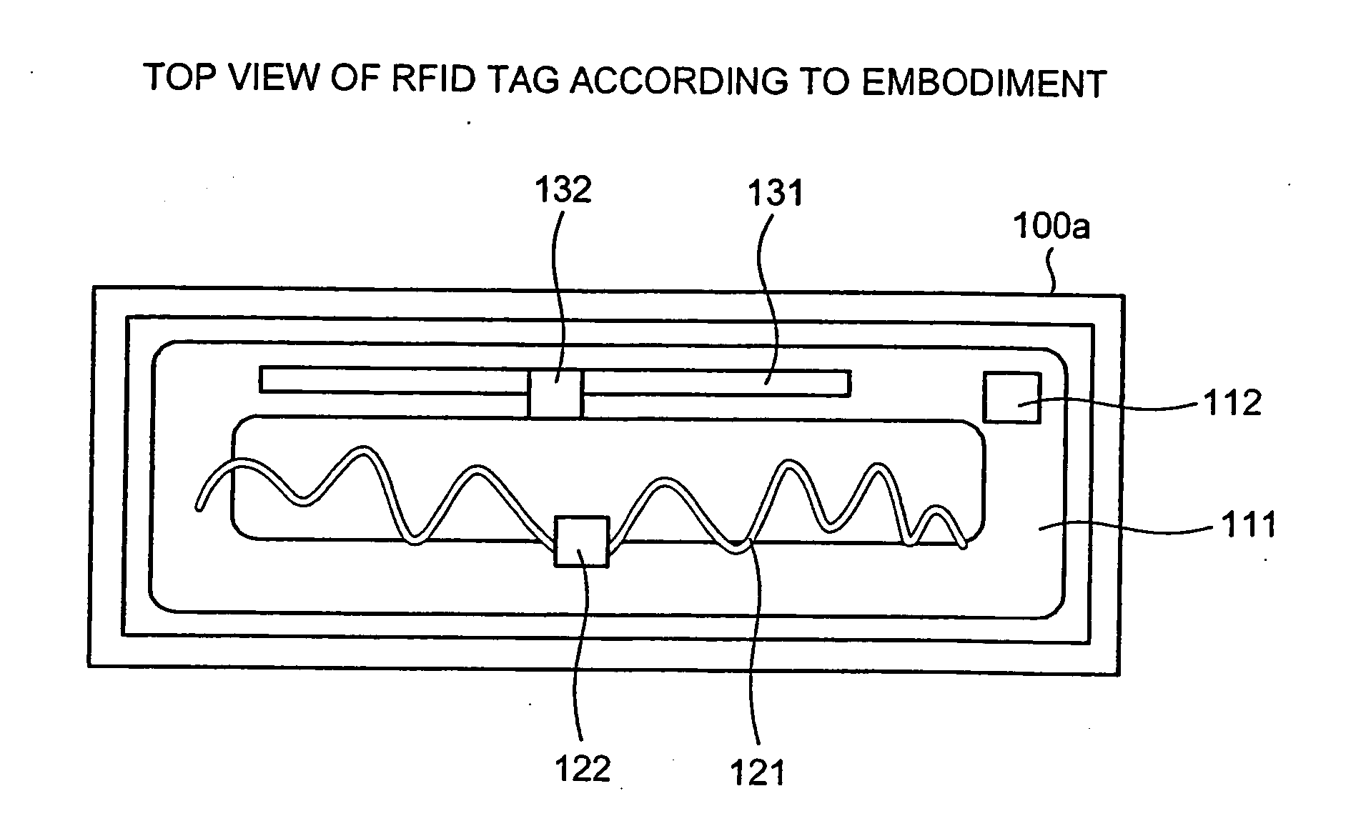
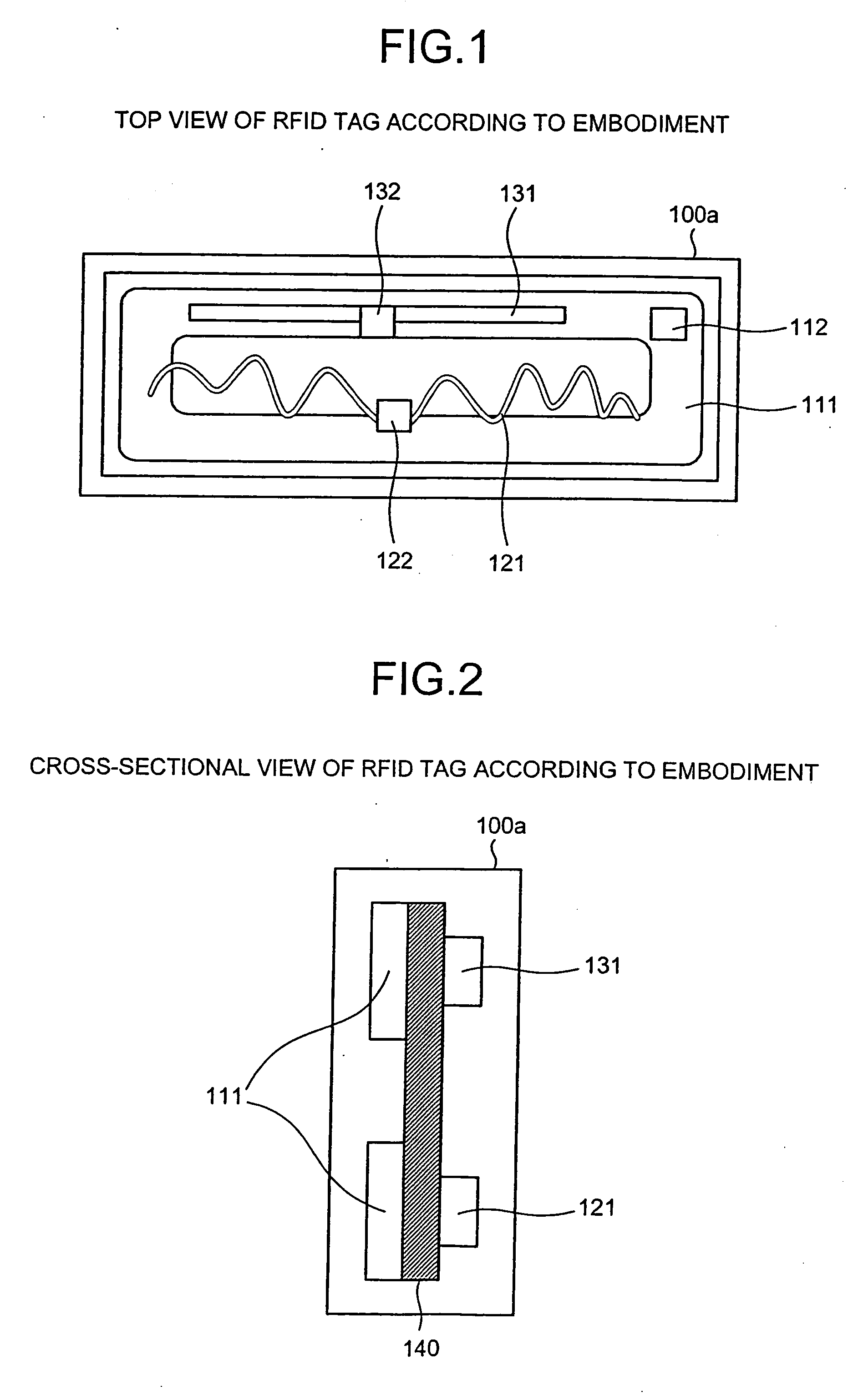
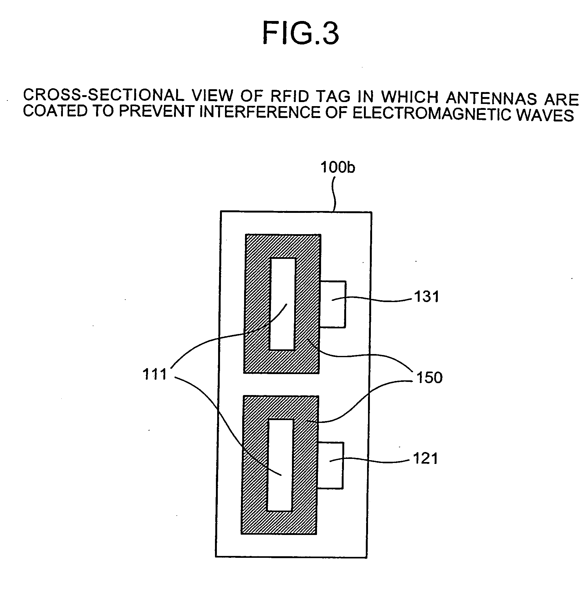
[0029] According to an aspect of the present invention, interference in a non-contact integrated circuit (IC) tag, for example, in a radio frequency identification (RFID) tag, (hereinafter simply referred to as a “tag,” between antennas is prevented by one or more insulator spacer(s) and / or insulator coating(s). Therefore, a plurality of antennas, each accepting different frequencies, can be freely arranged in a tag, so that the antennas can occupy a minimum area. Thus, for example, an RFID tag that accepts a plurality of frequency bands and provides sufficient performance in a compact size can be provided. The embodiments described herein use a passive RFID ...


PUM


Abstract

A non-contact integrated circuit (IC) tag accepts a plurality of frequency bands and provides sufficient performance in a compact size by freely arranging a plurality of antennas therein such that the antennas occupy a minimum area and by preventing interference between the antennas with an insulator.

Description

CROSS-REFERENCE TO RELATED APPLICATIONS [0001] This application claims the benefit of Japanese Application No. 2005-116142, filed Apr. 13, 2005, in the Japan Patent Office, the disclosure of which is incorporated herein by reference. BACKGROUND OF THE INVENTION [0002] 1. Field of the Invention [0003] The present invention relates to a radio frequency identification (RFID) tag provided with a plurality of antennas, and a method of arranging the antennas in the RFID tag. More specifically, the present invention relates to an RFID tag that accepts a plurality of frequency bands and provides sufficient performance in a compact size, and an antenna arranging method thereof. [0004] 2. Description of the Related Art [0005] In recent years, RFID tags are garnering attention as a product identification technology that can replace conventional barcode functions. It is expected that this technology will not only replace the barcode functions, but also drastically innovate conventional methods ...

Claims


Application Information

Patent Timeline
IPC IPC(8): G08B13/14H01Q5/10
CPCG06K19/072G06K19/07767G06K19/07749
Inventor TOMIOKA, TAKESHIOCHIAI, TAKANAO
Owner FUJITSU LTD
Why Eureka
Try Eureka