Heat sink

a technology of heat sink and heat sink, which is applied in the direction of indirect heat exchangers, heat exhanger fins, lighting and heating apparatus, etc., can solve the problems of insufficient forced convection to remove heat, affecting the efficiency of heat removal, and increasing heat, so as to achieve enhanced heat dissipation efficiency and return-flow speed

Inactive Publication Date: 2006-10-26
DELTA ELECTRONICS INC
View PDF10 Cites 24 Cited by
  • Summary
  • Abstract
  • Description
  • Claims
  • Application Information

AI Technical Summary

Benefits of technology

[0012] An object of the invention is to provide a heat sink with high heat dissipation efficiency under high heat loadings.
[0013] Another object of the invention is to provide a heat sink with high heat dissipation efficiency when installed in any direction.
[0014] Yet another object of the invention is to provide a heat sink which prevents dry outs and hot spots from occurring.
[0021] Moreover, since the bottom of the small vapor chambers and / or small sectors are composed of connecting wicks (heat-absorptive portion), the working fluid in each small vapor chamber are in fluid communication, and thus the possibility of hot spots occurring is lowered, and the heat is evenly distributed to each small vapor chamber and / or small sector.
[0023] The vapor chamber in the heat sink according to the invention is composed of a plurality of small vapor chambers and / or small sectors, and therefore the return-flow path of the working fluid is short, and the return-flow speed and heat dissipation efficiency are enhanced.

Problems solved by technology

However, this correspondingly produces more heat, and therefore relying on natural or forced convection is insufficient to remove heat.
However, the conventional heat sinks with fins have some problems that do affect the efficiency of heat removal.
For instance, a deficiency in temperature gradient due to the temperature difference between the fin surfaces and the heat sink airflow being only 5-10 degrees Celsius; the heat resistance problems due to the material and structure of the heat sink and low fin efficiency that is less than 70%.
These problems are the root causes for the conventional heat sinks not able to increase its' heat dissipation efficiency and further unable to remove the heat produced by electronic components sufficiently.
Nonetheless, the path for the working fluid to return to the chamber is long.
In addition, the single phase state (only vapor) in the heat conductive mechanism and the long return path can make the fins except the outmost fins ineffective.
Under this condition, the effective dissipating surface is greatly reduced and hence lowers the effectiveness of the heat sink.
Since gravity is the return-flow mechanism used in this application, direction problems do exist.
That is, when the installation direction of the heat sink changes, the return-flow mechanism becomes inoperable.
However, this technology did not solve the problem that exists in the U.S. Pat. No. 6,490,160, where the dry out occurs and all but the outmost hollow fins are inoperable under a high heat-loading condition, which lowers the dissipation efficiency.

Method used


Image

  • Heat sink
  • Heat sink
  • Heat sink

Examples


Embodiment Construction

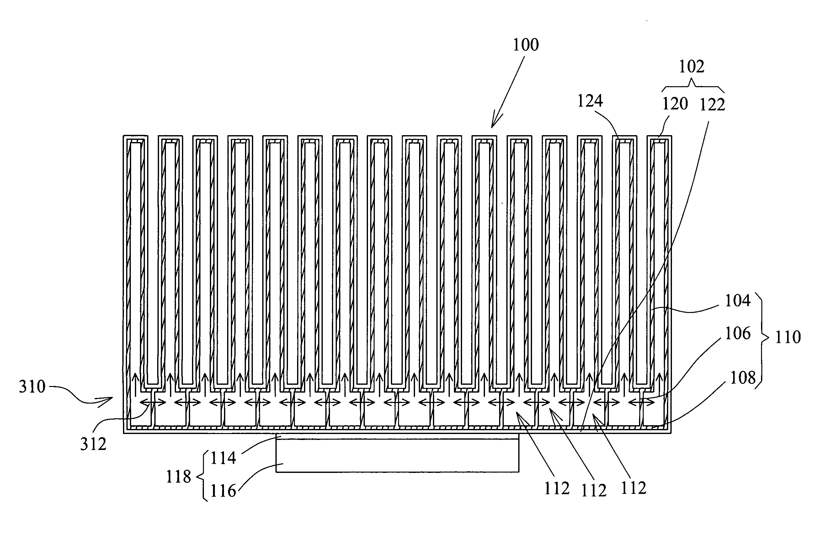
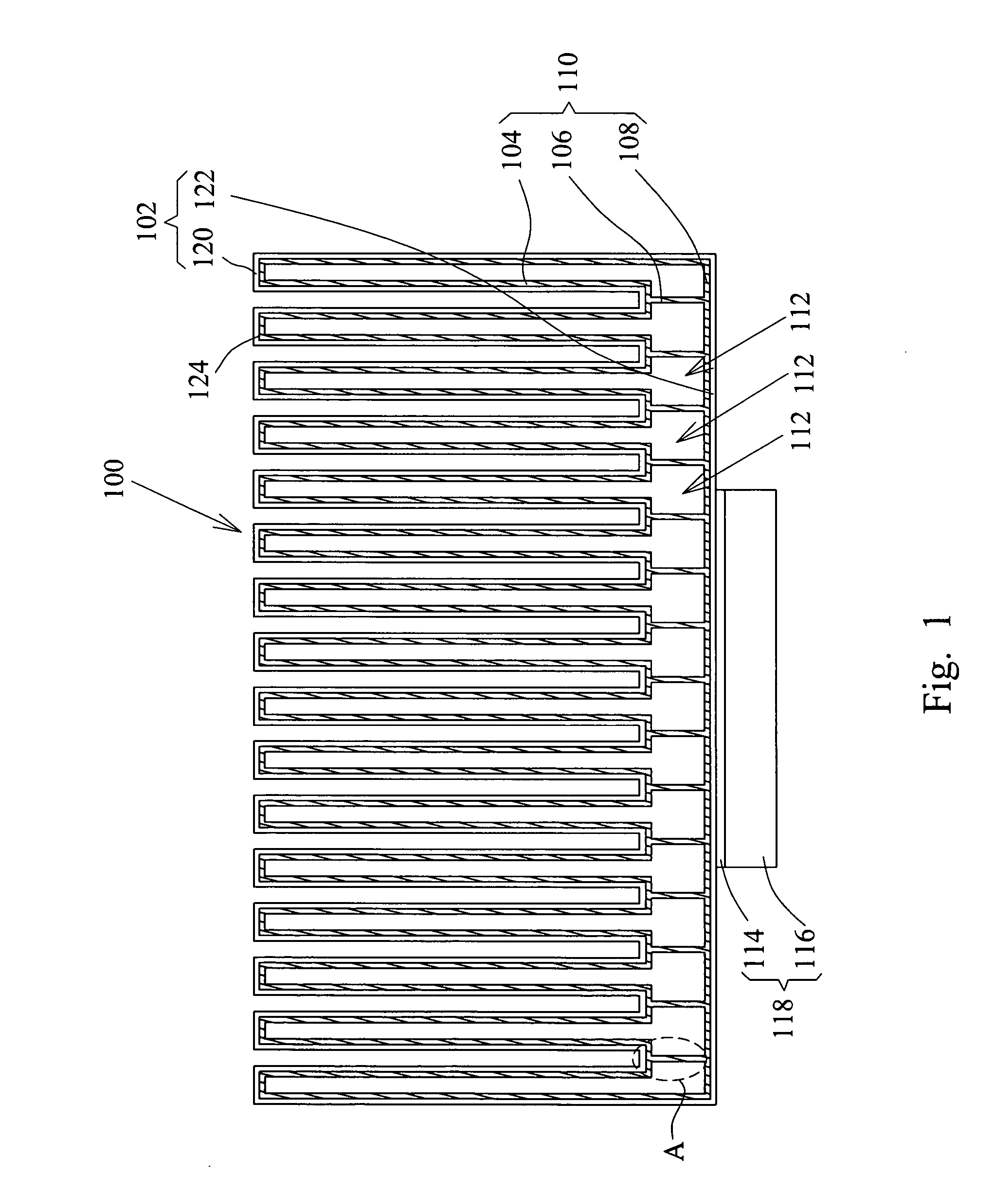
[0028] Referring to FIG. 1, a heat sink 100 includes a main body 102 and a plurality of porous structures 110 inside the main body 102, wherein the main body 102 has a closed room 124 formed therein.

[0029] The main body 102 has a plurality of hollow protrusions 120 and a base 122 connecting to a heat source 118. The shape and / or size of the base 122 varies in accordance with the placement of the protrusions 120 and the shape of the heat source 118. Each protrusion 120 is hollow and has two ends; the end proximate the base 122 has an opening and the other end is closed. The protrusions 120 are in a shape of fin, column, lamella, cone, or lump; and in a form of curve, arch, slant, vertical, or any other form. The protrusions 120 and the base 122 of the main body 102 can be one-piece molded or jointed by soldering, engaging, embedding, adhering, or a combination of any of the methods listed thereof. Moreover, the closed room 124 can be divided into a plurality of vapor chambers 112 by...


PUM


Abstract

A heat sink including a main body and a plurality of porous structures is disclosed. The main body has a plurality of hollow fins and a base. The fins and the base form a closed room. The porous structures are set on the interior surfaces of different fins, and are connected to the base. Each porous structure defines a vapor chamber.

Description

RELATED APPLICATIONS [0001] This application is a continuation-in-part of U.S. application Ser. No. 11 / 007,192, filed Dec. 09, 2004, which claims priority to Taiwan Application Serial Number 93106818, filed Mar. 15, 2004, the disclosure of which is hereby incorporated by reference herein in its entirety.BACKGROUND OF THE INVETION [0002] a) Field of the Invention [0003] The invention relates to a heat sink and, more particularly, to a heat sink that is able to dissipate heat quickly and efficiently. [0004] b) Description of the Prior Art [0005] With the advancement of electronic technology, the electronic components are miniaturized and densely packaged. However, this correspondingly produces more heat, and therefore relying on natural or forced convection is insufficient to remove heat. [0006] The conventional method of removing heat generated from electronic components is to conduct the heat from a heat source to a heat sink and then to dissipate the heat to the surroundings throug...

Claims


Application Information

Patent Timeline
Patent Type & Authority Applications(United States)
IPC IPC(8): F28D15/00
CPCF28D15/0233F28F2215/06F28D15/046
Inventor LEE, YI-SHENG
Owner DELTA ELECTRONICS INC
Why Eureka
Try Eureka