Light emitting diode bulbs with high heat dissipating efficiency

a technology of light-emitting diodes and led bulbs, which is applied in the direction of cathode-ray/electron beam tube circuit elements, light-emitting devices for light sources, lighting and heating apparatus, etc., can solve the problems of low reliability, loss of energy-saving effect, and failure of leds,

Inactive Publication Date: 2013-06-27
HON HAI PRECISION IND CO LTD
View PDF11 Cites 31 Cited by
  • Summary
  • Abstract
  • Description
  • Claims
  • Application Information

AI Technical Summary

Benefits of technology

[0005]However, LEDs employed in illumination devices must be equipped with means with high heat dissipating efficiency to give play to above mentioned advantages. Otherwise, the luminous efficiency and lifespan of LEDs will be heavily discounted, thereby leading to loss of energy saving effect, low reliability, light attenuation and failure of the LEDs. As such, it is very important to realize the heat generation of the LED bulbs, and to use proper heat conductive material in LED bulbs and to sort out scientific heat dissipating solutions.
[0005]However, LEDs employed in illumination devices must be equipped with means with high heat dissipating efficiency to give play to above mentioned advantages. Otherwise, the luminous efficiency and lifespan of LEDs will be heavily discounted, thereby leading to loss of energy saving effect, low reliability, light attenuation and failure of the LEDs. As such, it is very important to realize the heat generation of the LED bulbs, and to use proper heat conductive material in LED bulbs and to sort out scientific heat dissipating solutions.
[0005]However, LEDs employed in illumination devices must be equipped with means with high heat dissipating efficiency to give play to above mentioned advantages. Otherwise, the luminous efficiency and lifespan of LEDs will be heavily discounted, thereby leading to loss of energy saving effect, low reliability, light attenuation and failure of the LEDs. As such, it is very important to realize the heat generation of the LED bulbs, and to use proper heat conductive material in LED bulbs and to sort out scientific heat dissipating solutions.

Problems solved by technology

Otherwise, the luminous efficiency and lifespan of LEDs will be heavily discounted, thereby leading to loss of energy saving effect, low reliability, light attenuation and failure of the LEDs.
As such, the heat sinks are usually big and heavy, thereby unfavorable for miniaturization design thereof.
Further, due to usual LED bulbs need to be configured with a great temperature gradient along heat conducting path thereof, load diversity of the heat sink will lead to low utilization rate and rise of temperature, and the rise of temperature will undesirably lead to light attenuation of the LEDs.
As such, considering about traditional bulb size and receptacle loading, usual LED bulbs are designed with low power and unsatisfied for high power illumination.
As such, the circuit boards may be overheated and aged rapidly.

Method used


Image

  • Light emitting diode bulbs with high heat dissipating efficiency
  • Light emitting diode bulbs with high heat dissipating efficiency
  • Light emitting diode bulbs with high heat dissipating efficiency

Examples


first embodiment

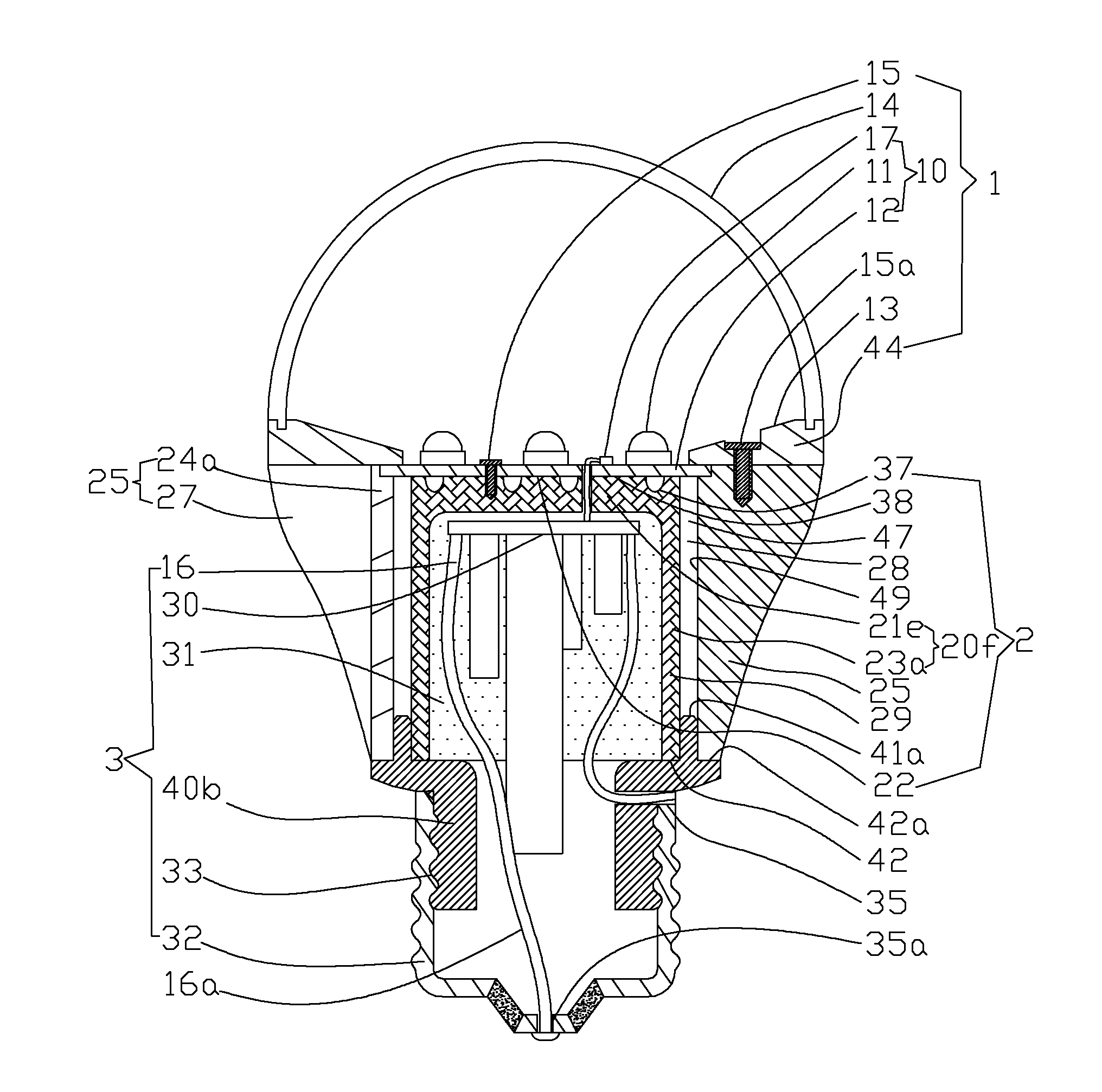
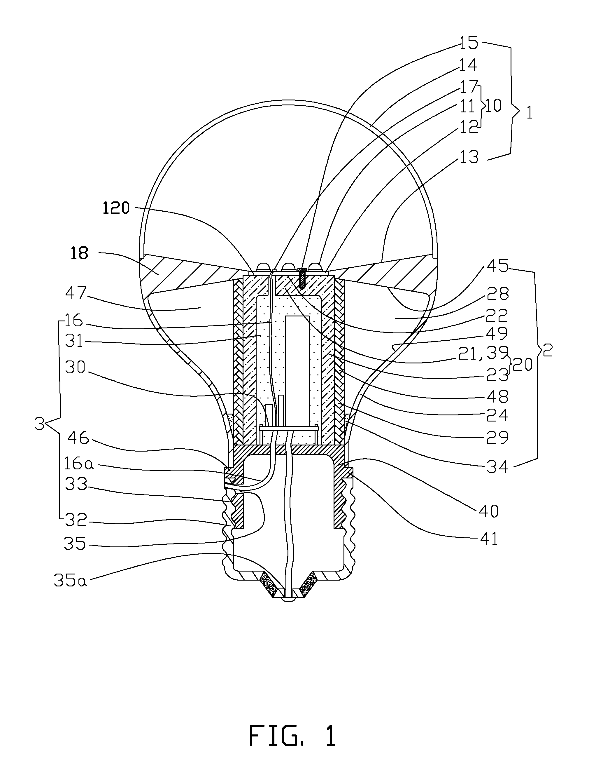
[0021]Referring to FIG. 1, an LED bulb in accordance with the present disclosure, includes an optical section 1 arranged a top portion of the LED bulb, a heat dissipation section 2 arranged a middle portion of the LED bulb, and an electrical section 3.

[0022]The optical section 1 is arranged in font of the heat dissipation section 2 and the electrical section 3. The optical section 1 includes a light source 10 having at least one LED 11 and a light guider 14. The light guider 14 is configured for adjusting luminance distribution and light emitting properties of the LED 11, and protecting the light source 10 from ambient environment.

[0023]The light source 10 further includes a substrate 12 wherein both the at least one LED 11 and a plurality of electrodes 17 are mounted on and electrically connected to an electrical circuit formed on one side of a heat conductive plate 120 of the substrate 12. The at least one LED 11 is constructed by at least one encapsulated LED die. A thermal conta...
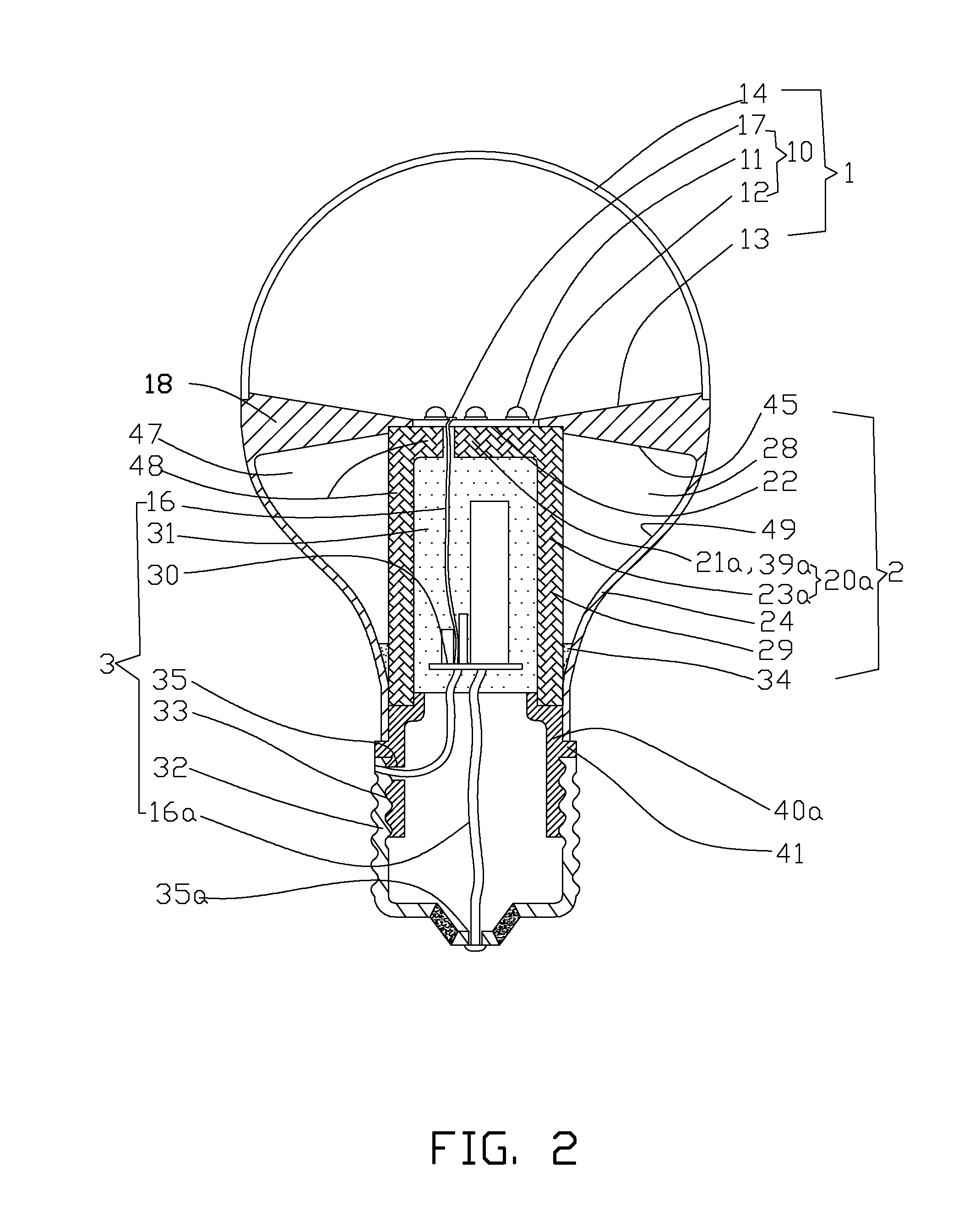
second embodiment

[0037]When the LED bulb of the second embodiment projects light upwardly through the light guider 14, heat generated by the light source 10 and the circuit board 30 will be transferred to the working fluid 34 contained in the porous wick structure 29 of the sleeve 20a, and the working fluid 34 will be heated and vaporized by the heat, thereby being immediately converted into saturated vapor and rapidly expanding to occupy the vapor passage 47. Then the condensing sector 49 will cool the saturated vapor in the chamber 28 and convert the saturated vapor back to liquid state working fluid 34 with subcooled temperature. Then the liquid state working fluid 34 will fall down under gravity along the tapering inner sidewall of the shell 24, and successively be absorbed by the porous wick structure 29. Thereafter, the liquid state working fluid 34 is drawn back into the wick structure 29 for absorbing heat generated by the light source 10 and the circuit board 30 again.

[0038]When the LED bul...


PUM


Abstract

An exemplary LED bulb includes a top optical section, a middle heat dissipation section, and a bottom electrical section. The optical section includes a light source and a light guider. The light source further includes a substrate and at least one LED arranged on the substrate. The heat dissipation section includes a sleeve at a rear of the optical section and a chamber. The sleeve has a tube portion and a sealed end with a heat absorbing surface thermally contacting the substrate. A porous wick structure is arranged on the outer sidewall of the tube portion and contains working fluid therein. The chamber has an annular configuration defined between an inner side surface of an LED bulb shell and an outer side surface of the sleeve. The electrical section includes a threaded cap arranged at a bottom portion of the LED bulb, and a circuit board received in the sleeve.

Description

BACKGROUND[0001]1. Technical Field[0002]The present disclosure generally relates to light emitting diode (LED) bulbs, and particularly to an LED bulb with high heat dissipating efficiency.[0003]2. Description of Related Art[0004]Due to that traditional illuminating light sources are energy consuming, LEDs have a potential of being widely used as substitute for traditional illuminating light sources because of high luminous efficiency, energy saving, long lifespan, environmental friendly property, low driving voltage, low temperature luminescence, fast starting, small volume, high directivity, excellent quake proof performance and shock resistance thereof.[0005]However, LEDs employed in illumination devices must be equipped with means with high heat dissipating efficiency to give play to above mentioned advantages. Otherwise, the luminous efficiency and lifespan of LEDs will be heavily discounted, thereby leading to loss of energy saving effect, low reliability, light attenuation and...

Claims


Application Information

Patent Timeline
Patent Type & Authority Applications(United States)
IPC IPC(8): F21V29/00
CPCF21V29/006F21K9/1355F21K9/50F21V3/02F21V29/87F21V13/02F21V23/006F21Y2101/02F21V29/507F21V7/041F21K9/23F21K9/238F21K9/60F21Y2115/10F21K9/232F21V29/51F21V29/74
Inventor LIU, TAY-JIAN
Owner HON HAI PRECISION IND CO LTD
Why Eureka
Try Eureka