
Hybrid heat sink and hybrid heat sink assembly for power module

a technology of hybrid heat sink and power module, which is applied in the direction of indirect heat exchangers, lighting and heating apparatus, and modifications by conduction heat transfer, etc., can solve the problems of dissipation problems, failure of power devices or devices, and reduced service life, so as to achieve reliable and stable heat dissipation, large heat dissipation area, and large thermal capacity

Active Publication Date: 2013-06-20
DELTA ELECTRONICS (SHANGHAI) CO LTD
View PDF24 Cites 31 Cited by
  • Summary
  • Abstract
  • Description
  • Claims
  • Application Information

AI Technical Summary

Benefits of technology

The present invention has two heat dissipation units, one made of metal and the other a heat-pipe type. These units are combined to create a compact, efficient heat sink that has both large thermal capacity and rapid heat dissipation. The power module is secured on a base, making it easy to mount and transport. The result is a heat sink that is small, light, and has excellent heat dissipation efficiency.

Problems solved by technology

Since if the heat yielded by the power device can not be dissipated in time and efficiently, a temperature of the power device will be raised, the effectiveness will be lowered and the service life will be reduced in an unserious case, it would result in failure of the power device or device explosion in a serious case.
Therefore, the power device package factory and the user of the power device are always puzzled in the heat dissipation problem.
However, as a result, a distance between the power devices is relatively large, electrical connection distance therebetween is increased, the leakage inductance is increased, and efficiency is relatively low, it has unfavourable effect on the performance and service life of the power devices, and more unfavourable especially for parallel topology of a plurality of the IGBTs.
And for a power module with large power, since thermal flux of a single power device is large, the heat dissipation can not be solved in the conventional all-metal heat dissipation manner.

Method used


Image

  • Hybrid heat sink and hybrid heat sink assembly for power module
  • Hybrid heat sink and hybrid heat sink assembly for power module
  • Hybrid heat sink and hybrid heat sink assembly for power module

Examples


Embodiment Construction

[0037]Hereinafter, technical solutions of the present invention will be described in details in conjunction with the drawings and the preferred embodiments, so as to further understand objects, solutions, and effects of the present invention but not to limit protection scopes of appended claims of the present invention.

[0038]A hybrid heat sink 100 of the present invention is applicable to a power module, such as a SVG, a MVD, an UPS, a wind power converter, and so on, with a large power and a high thermal flux and in which a power device is compactly arranged together for heat dissipation.

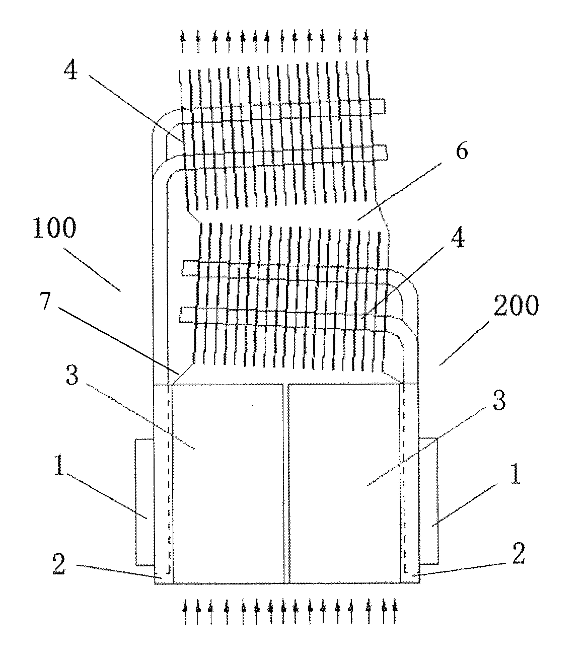
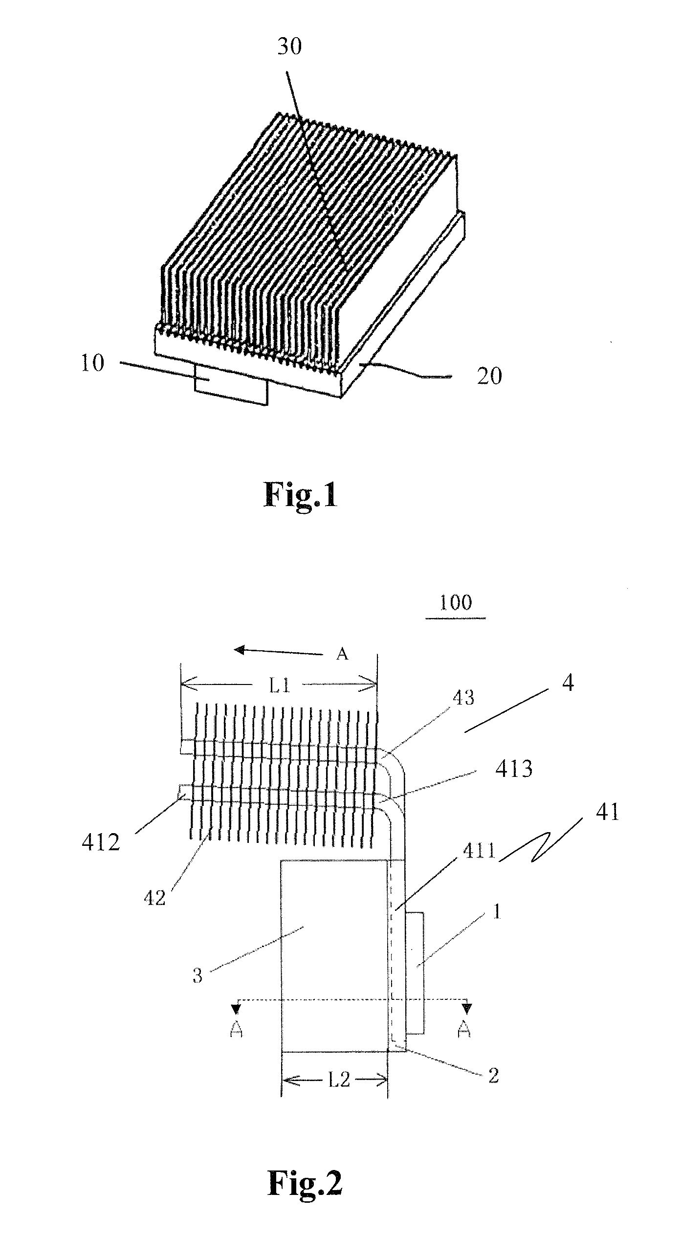
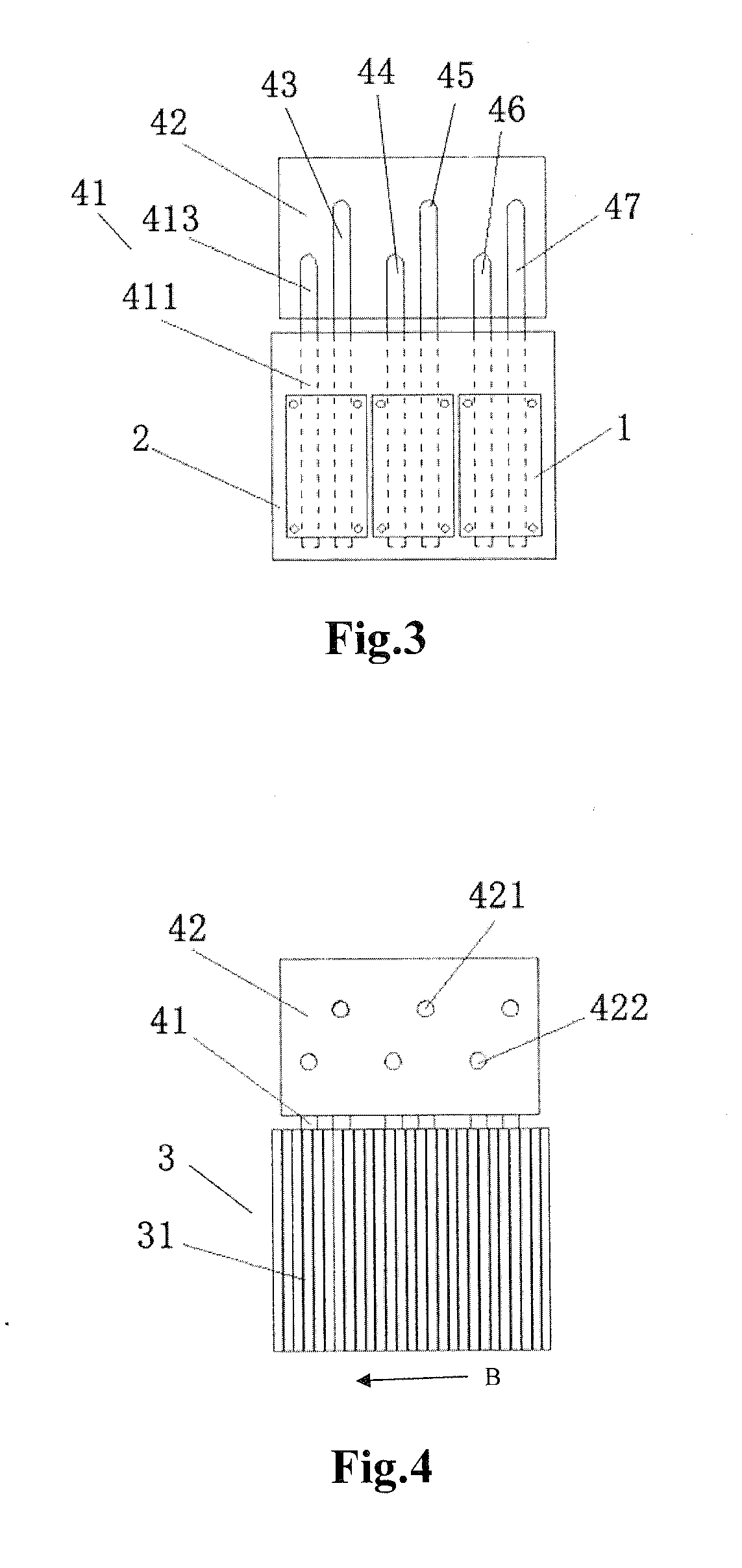
[0039]Referring to FIGS. 25, the hybrid heat sink 100 of the present invention comprises a base 2, a first heat dissipation unit 3, and a second heat dissipation unit 4, a power module 1 is located on one side of the base 2, the first heat dissipation unit 3 is located on the other side of the base 2, wherein the other side is a side opposite to the one side (referring to FIG. 2). The first heat di...


PUM


Abstract

Disclosed are a hybrid heat sink and a hybrid heat sink assembly for a power module. The hybrid heat sink comprises a base provided with at least one power module on one side thereof, a first heat dissipation unit being a first heat dissipation fin group which is composed of a plurality of heat dissipation fins intervally arranged and is located on the other side of the base, and a second heat dissipation unit comprising a plurality of heat pipes and a second heat dissipation fin group. Each of the heat pipes comprises an evaporating section provided in the base and close to the power module, a condensing section, and an adiabatic section located between the evaporating section and the condensing section and comprises an extension portion and a folding portion, the second heat dissipation fin group is provided on the condensing sections.

Description

CROSS-REFERENCE TO RELATED APPLICATIONS[0001]This non-provisional application claims priority under 35 U.S.C. §119(a) on Patent Application No. 201110424870.8 filed in P.R. China on Dec. 16, 2011, the entire contents of which are hereby incorporated by reference.FIELD OF THE PRESENT INVENTION[0002]The present invention relates to a heat dissipation device, and specifically, to a hybrid heat sink and a hybrid heat sink assembly for a power module in which an all-metal type heat sink and a heat-pipe type heat sink are combined together.BACKGROUND ART[0003]With rapid development of electronic technology, a power density of a power device becomes higher and higher. When the power device is rapidly and frequently switched between turn-on and turn-off, yielded heat is also more and more. In order to assure the power device to work normally, it must dissipate heat in time and efficiently. Since if the heat yielded by the power device can not be dissipated in time and efficiently, a tempera...

Claims


Application Information

Patent Timeline
Patent Type & Authority Applications(United States)
IPC IPC(8): H05K7/20
CPCH01L23/427H01L23/467F28D15/0275H01L2924/0002H01L2924/00H05K7/2039H05K7/20909H05K7/20918H05K7/20936
Inventor TONG, AIXINGLIU, TENGYING, JIANPING
Owner DELTA ELECTRONICS (SHANGHAI) CO LTD
Learn More